


Chapter 4 - Signals and Troubleshooting
DCS 500B / DCP 500B Operating Instructions
IV A 4 - 13
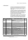
Code
seven
segm.
display
Text on
LCD of control panel
CDP 31x
Definition /
Possible source
Signal
number
(ALARM_WORD_1/2)
Remark
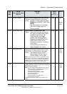
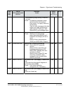
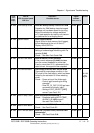
A 108
RAM-backup failed
Alarm No Battery Backup Function for RAM
Capacitor for RAM backup has discharged
(perhaps unit has been stored for too long
without the electronics voltage switched
on?); load capacitor by leaving unit electron-
ics switched on for a lengthy period.
11104 bit 7
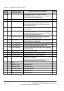
A 110
System restart
Alarm System Restart
Signal is filed in fault memory (fault logger),
but not displayed at the unit or the LC-
Display of the CDP 31x.
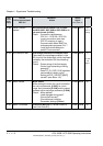
A 118
Mains underv.alarm
Alarm Mains Undervoltage (AC)
Setting of undervoltage monitoring with Pa-
rameter
[P 508]
Check: - See also Fault Code F 29.
11104 bit 10
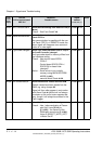
A 120
Arm.curr.dev.alarm
Alarm Armature Current Deviation
If the current reference [P 10405] deviates
from the current feedback for more than
5 sec by more than 20 %, referenced to the
rated current, this signal will be outputted.
11104 bit 13
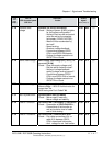
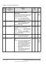
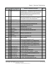
A 121
Ext.Overvolt.Alarm
Overvoltage protection DCF 506 has acted
There was an overvoltage condition in the
DC circuit of the field supply, which had been
limited by the activation of a free wheeling
circuit.
Check: - Power wiring of the field supply
- Control logic according to wiring
example?
- Does PP_DI_OVP [1216] has been
connected to a binary input?
- Setting of OVP_SELECT [1217]
correct? (see Fault 121)
11105 bit 6
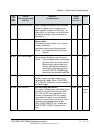
S21.232
and
higher
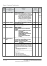
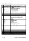
A 123
Motor 2 temp. alarm
Alarm Overtemperature MOTOR 2
Check: - Parameter setting MOT2.TEMP_
ALARM_L
[P 1602] correct?
See also Fault Code
F 6.
11104 bit 8
A 124
Motor 2 overl alarm
Alarm Overload MOTOR 2 (Thermal Model 2)
Check: - See Fault Code F 7.
11104 bit 9
A 126
Conv.FAN ack.alarm
Alarm No (Thyristor Power) Converter FAN
Acknowledge
Check: - See Fault Code F 50.
11104 bit 12
3ADW000055R0401_DCS500B_Operating Instruction_e_d