Chapter 3 - Handling of Control Panel CDP 31x
DCS 500B / DCP 500B Operating Instructions IV A 3 - 13
3.12 Selecting output pins
Note for CDP 310 / CDP 311:
Newly selected actual signals will be used for display until the elec-
tronics power supply is switched OFF.
Note for CDP 312:
If there is a need for permanent display of the newly selected pin
(e.g. after having switched OFF and ON again the electronics
power supply), BACKUPSTOREMODE (see chapter 3.5) should
be performed in order to save the values to the backup memory
before switching OFF the electronics power supply.
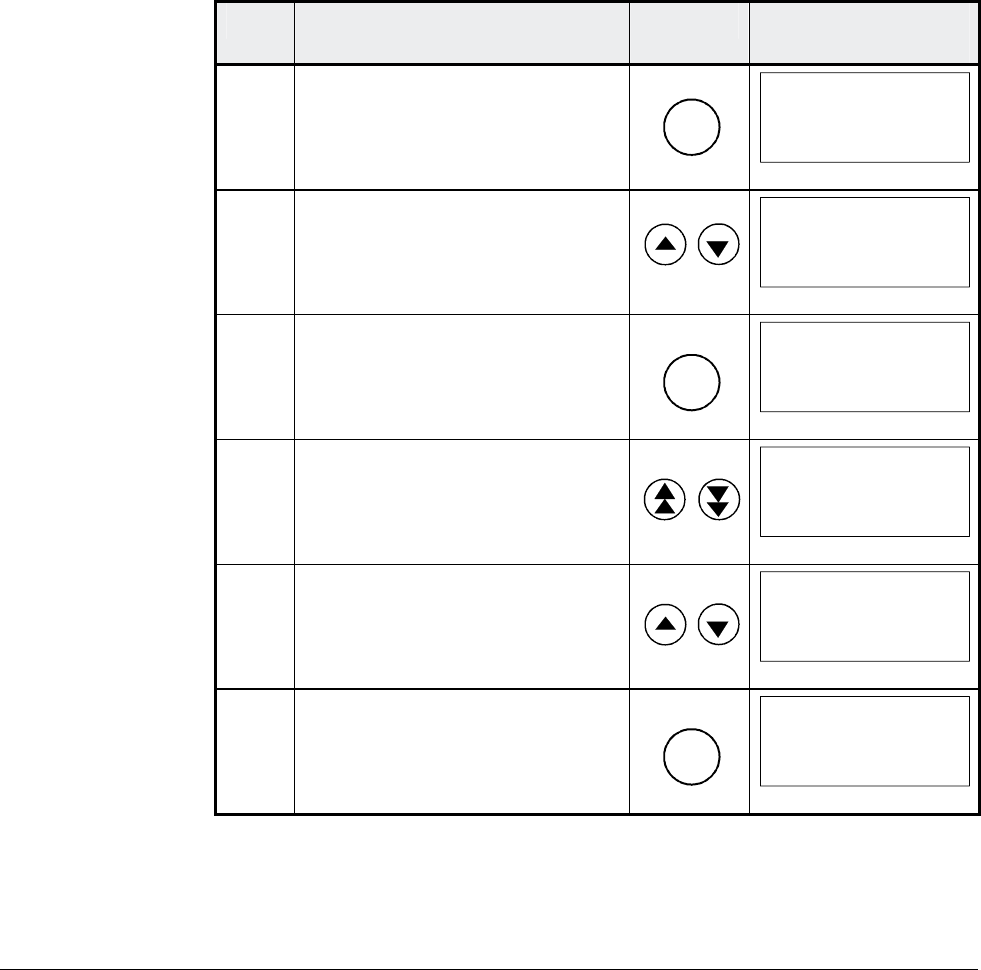
Step Function Press key Display after key is
pressed
1.
To enter the Actual Signal
Display Mode
ACT
0 L 0.0 rpm 00
SPEED AC 0.0 rpm
CONV CUR 0 A
U ARM AC 0 V
_
2. To select the desired line.
0 L 0.0 rpm 00
SPEED ACT FILT
CONV CURR ACT
U ARM ACT
_
3. To get acces to the desired line.
ENTER
0 L 0.0 rpm 00
121 SPEED MEASUREMEN
03 SPEED ACT FILT
0.0 rpm
4. To select a different group.
0 L 0.0 rpm 00
120 SPEED CONTROLLER
01 ERR:OUT
0.0 rpm
5. To select a element.
0 L 0.0 rpm 00
120 SPEED CONTROLLER
04 SPC:OUT
0.0 %
6. To accept the selection and to
return to the Actual Signal
Display Mode.
ENTER
0 L 0.0 rpm 00
SPC:OUT 0.0 %
CONV CUR 0 A
U ARM AC 0 V
_
3ADW000055R0401_DCS500B_Operating Instruction_e_d
