


Chapter 4 - Signals and Troubleshooting
IV A 4 - 12 DCS 500B / DCP 500B Operating Instructions
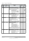
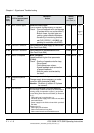
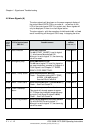
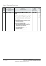
4.5 Alarm Signals (A)
The alarm signals will be shown on the seven segment display of
the control board SDCS-CON-x as codes A . . as well as on the
LCD of the control panel CDP 31x as plain text. Alarm signals will
only be displayed, if there is no fault signal active.
The alarm signals - with the exception of
A 101 and A 102 - will not
result in switching off the signal 10910 resp. in stopping the drive.
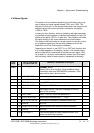
Code
seven
segm.
display
Text on
LCD of control panel
CDP 31x
Definition /
Possible source
Signal
number
(ALARM_WORD_1/2)
Remark
A 101
Start inhibition
Alarm Start Inhibition
Pin 908 (START_INHIBIT) is set to logical
"1“; drive cannot be switched ON.
When pin is set to logical "0“, the alarm sig-
nal will be reset.
11104 bit 0
A 102
Emergency stop
Alarm EMERGENCY STOP
Pin 906 has a logical "0" level; for signal re-
set, see introductory remarks in Chapter 4.4
"Fault Signals“ and Chapter 3.7 "EMER-
GENCY STOP RESETTING“.
11104 bit 1
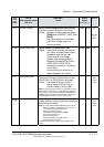
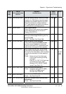
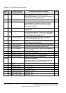
A 103
Motor 1 temp. alarm
Alarm Overtemperature MOTOR 1
Check: - Parameter setting MOT1.TEMP_
ALARM_L
[P 1402] correct?
See also Fault Code F 6.
11104 bit 2
A 104
Motor 1 overl.alarm
Alarm Overload MOTOR 1 (Thermal Model 1)
Check: - See Fault Code F 7.
11104 bit 3
A 105
Conv. overtemp.
alarm
Alarm Overtemperature Power Section
This signal will already appear at approx.
10 °C below the shutdown temperature ap-
plying for Fault Signal
F 4 (see P 10512).
Check: - See Fault Code
F 4.
11104 bit 4
A 106
Current reg blocked
Alarm Current Regulator/Controller blocked
Pin 404 (BLOCK) is set to logical "1“.
When pin is set to logical "0“, the alarm sig-
nal will be reset.
11104 bit 5
3ADW000055R0401_DCS500B_Operating Instruction_e_d