


Chapter 3 - Handling of Control Panel CDP 31x
DCS 500B / DCP 500B Operating Instructions IV A 3 - 5
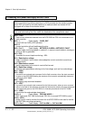
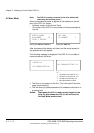
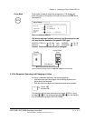
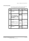
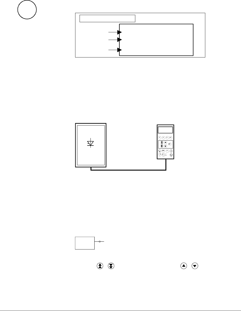
Drive Mode
DRIVE
Drive mode is used to check the configuration. The display will
show the type and ID-number of the drive to whom the CDP 31x is
connected to.
DCS500
ID-NUMBER 0
TOTAL 1 DRIVES
Device type
The ID-number
Total number
of drives in
the link
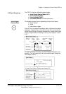
Drive Display
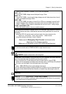
Display with CDP 310 / CDP 311
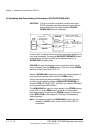
The factory-adjusted (default) values of the ID-numbers for the
CDP and the drive depend on the specific CDP type:
CDP 310 / CDP 311 ⇒ ID = 31 with DCS 500 ⇒ ID = 0
CDP 312 ⇒ ID = 0 with DCS 500B ⇒ ID = 1
Caution: These values should not be changed!
1 L 30.5 % 00
FLUX_REF 100%
EXMF_FLS 0 Log
ARMCURAC 147 A
CDI 300 link
(communication bus)
Control Panel
ID=0
DCS500
ID=31
Factory-adjusted (default) values for CDP 310 / CDP 311 with DCS 500
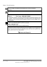
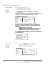
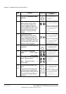
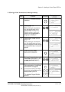
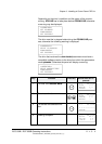
3.4 Pin/Parameter Selecting and Changing of Value
For input / parameter selection, the following applies:
• Ignore the two right-hand digits; the remaining digits are the
group and to be selected
• The two right-hand digits are the element and to be selected
DI7
10713
The selection can be done with the control panel CDP312, using
the keys
/ for the group and the keys / for the element
or a PC-based tool program CMT/DCS500B
Group 107
element 13
3ADW000055R0401_DCS500B_Operating Instruction_e_d