


Chapter 2 - Start-Up Instructions
IV A 2 - 6 DCS 500B / DCP 500B Operating Instructions
2.2 Scaling intra-unit signals
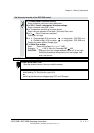
Make sure that the existing electronics supply voltage has been set on the SDCS-
POW-1 power supply board as well, using the SW1 switch.
If an encoder is being used as the speed feedback device, make sure that the correct
supply voltage has been seton the boards
SDCS-POW-1: ⇒ X3: / X4: / X5: SDCS-IOB-3: ⇒ S4
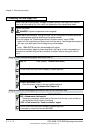
Switch on the power supply to the electronics section.
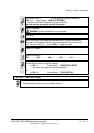
The display of Panel CDP 31x DCS 500
may show the following ** WARNING **
information: +Emergency stop
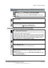
522 = GERMAN
[Only with the SDCS-CON-2 control board & the CDP 312 panel!]
Activates German texts on the display
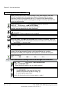
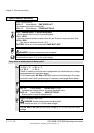
501 = Rated motor voltage
This is used to scale those parameters referring to the rated motor voltage, such
as field crossover point or maximum speed with e.m.f. control.
502 = Rated motor current
This is used to scale those parameters referring to the rated motor current, such
as current limitation or torque limitation.
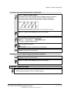
507 = Rated line voltage
This is used to scale those parameters referring to the line voltage, such as line
undervoltage.
Only when connection diagram 1 (Appendix A) is being used!
906 = 12502
„Emergency Stop“ de-activated
910 = 10908
No check-back signal from unit fan necessary
911 = 10908
No acknowledge signal from motor fan necessary
Set this only for units with a rated current ≥ 2050A!
517 = Rated power converter current
Enter numerical value from rating plate here
518 = Rated power converter supply voltage
Enter numerical value from rating plate here
519 = 45 Grad Celsius
Temperature monitoring of power section
520 = 4 ⇒ Size C4 has been selected
Coding for unit type
521 = 1 : Single bridge (2-Q) converter ⇒ on rating plate: DCS 501 xxxx
4 : Double bridge (4-Q) converter ⇒ on rating plate: DCS 502 xxxx
Coding for power section (bridge) type
3ADW000055R0401_DCS500B_Operating Instruction_e_d