


Chapter 4 - Signals and Troubleshooting
DCS 500B / DCP 500B Operating Instructions IV A 4 - 1
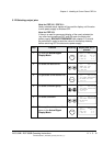
4.1 Display of status, alarm and fault signals
Categories of signals
and possibilities of
display
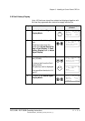
The signals (messages) to be available for thyristor power con-
verters series DCS 500B / DCF 500B or DCP 500 are subdivided
into five
categories:
General messages
Starting errors
F Fault signals
A Alarm signals
[112 . .] Status signals through parameters
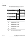
A seven segment display on the control board SDCS-CON-x of the
thyristor power converters series DCS 500B / DCF 500B or
DCP 500 is used to show general messages, starting errors, fault
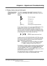
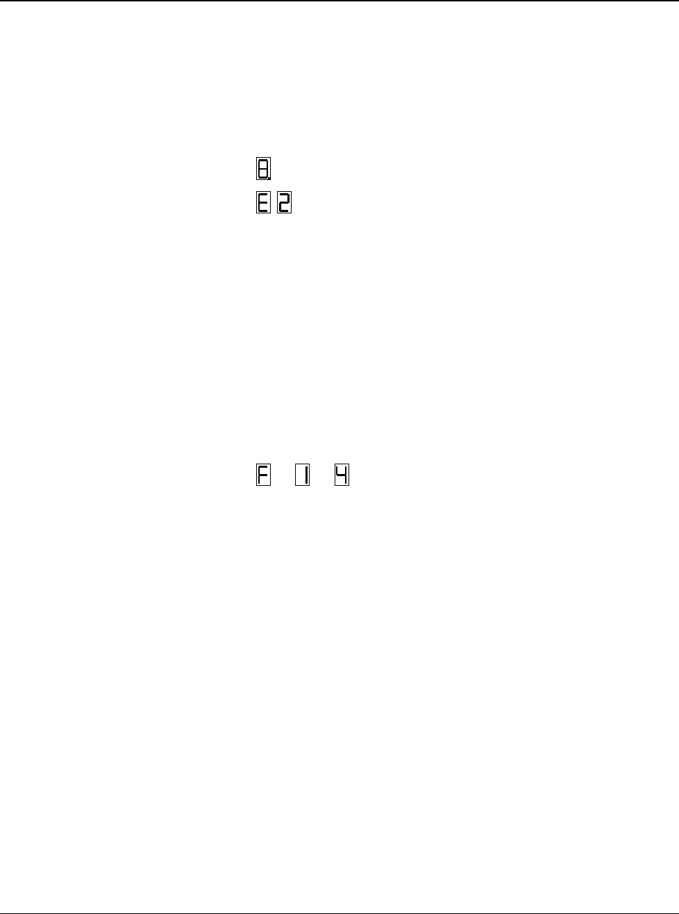
and alarm signals. The signals (messages) are displayed as codes.
If the codes consist of several parts, the characters/individual digits
will be indicated for 0.7 sec one after the other, e.g.:
0.7s
0.7s
0.7s
⇒
⇒
F 14 = Speed measurement fault
⇑ ⇐ ⇓
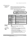
In addition to this the DCS 500B DCF 500B or DCP 500 combined
with the LCD of the control panel CDP 31x will be able to show the
fault and alarm signals as well as the status signals (selected by
signal numbers
[112 . .]) as clear text.
Note: The languages to be available for display as text depend
on the type of Control Panel and the Software version
( ⇒ Chapter „Handling of Control Panel CDP 31x“).
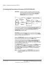
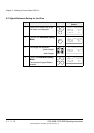
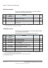
For subsequent evaluation via binary outputs or serial interfaces the
16 bit informations
FAULT WORD1 [11101], FAULT WORD2 [11102]
and
FAULT WORD3 [11103] as well as ALARM WORD1 [11104],
ALARM WORD2 [11105]
and ALARM WORD3 [11106] contain several
fault and alarm signals as a binary code.
Each fault and alarm signal is coded as an individual error code to
the
LATEST FAULT [11106] and LATEST ALARM [11107].
3ADW000055R0401_DCS500B_Operating Instruction_e_d