


Chapter 2 - Start-Up Instructions
DCS 500B / DCP 500B Operating Instructions IV A 2 - 13
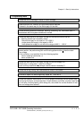
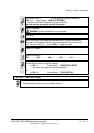
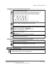
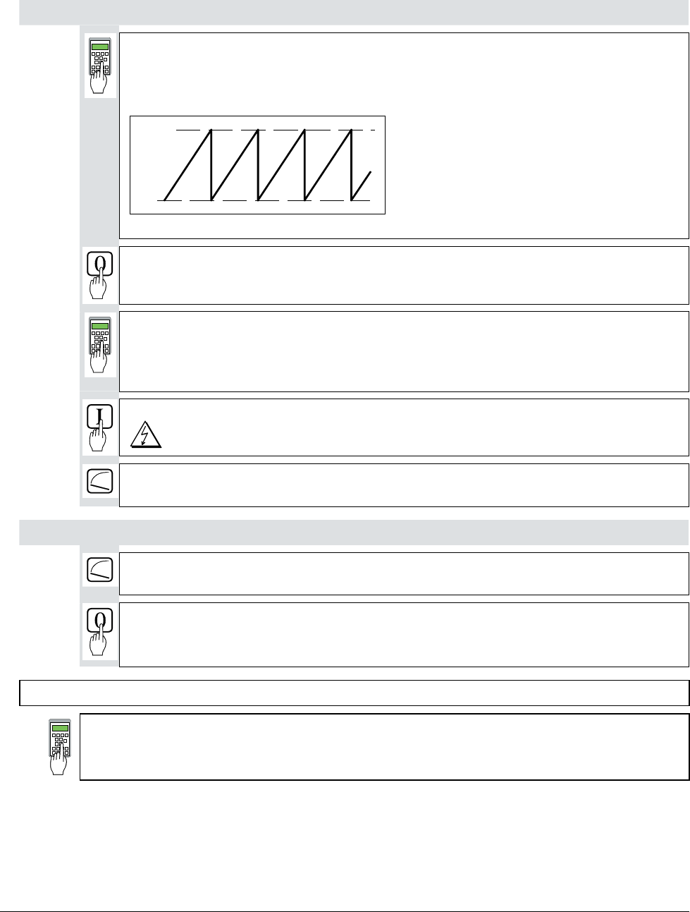
Only when an encoder (pulse encoder) is being used!
12104 = Content of pulse counter
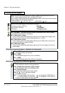
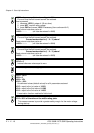
If the shape of the curve corresponds to the diagram below, this means
the wiring is correct and the pulses will be correctly evaluated [see
also documentation entitled „Technical Data“, Chapter I/O boards].
0
65535
Fig.: Curve shape of the encoder’s pulse counter for sense of rotation "forwards“
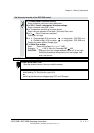
Switch OFF power, thus stopping the drive; drive coasts.
2101 = No. of encoder pulses
As specified on the encoder's rating plate
2102 = 3 Panel display: ENCODER A+-, B+-
Encoder is used for speed control.
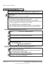
Switch ON power; start drive.
DANGER: System components now energized!
Drive should run at 10 % of the desired speed;
if possible, check with manual tacho.
Only when the e.m.f. signal is being used as speed feedback!
Drive should run at 10 % of the desired speed;
if possible, check with manual tacho.
Switch OFF power, thus stopping the drive; drive coasts.
CAUTION! Please don't forget!
11202 = SAVE MOT1 SET
Save the altered values in the non-volatile memory!
3ADW000055R0401_DCS500B_Operating Instruction_e_d