


Chapter 2 - Start-Up Instructions
IV A 2 - 8 DCS 500B / DCP 500B Operating Instructions
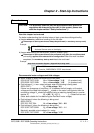
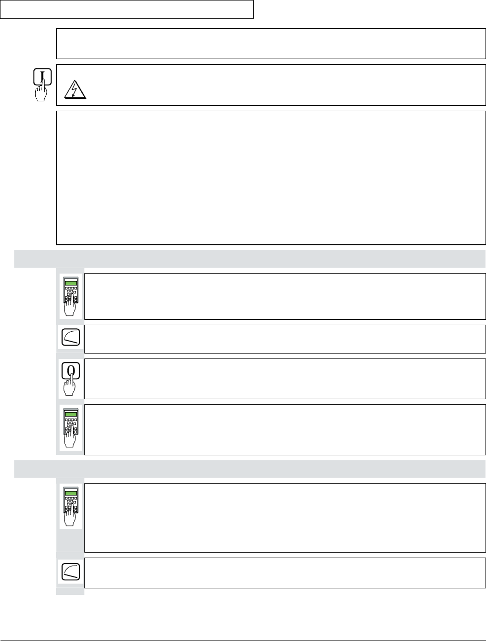
2.3 Presetting the field supply unit
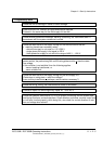
Make sure that existing supply voltages for power section, field supply unit (field ex-
citer) and field winding, fan, etc. match the rated data of the components used.
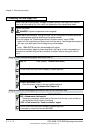
Switch ON power.
DANGER: System components now energized!
Please wait a few moments. During this time, the unit compares the phase sequence
set in the parameter with that obtaining at the power section.
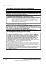
If the unit outputs the "Phase sequence fault of power section“ signal (F 38):
- switch off unit completely and disconnect from the mains, interchange two phases at
the input, and start again from the beginning of this chapter.
or
- enter: 506 = R-T-S and then acknowledge fault signal.
Unit will automatically adapt to phase sequence; this signal is to be interpreted as in-
formation to the effect that the fans' direction of rotation may be wrong for size-C4
units.
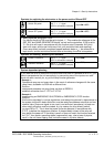
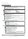
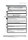
Only for uncontrolled field supply with SDCS-FEX-1!
505 = 1 Panel display: DIODE FIELD EXCIT
Check field current and field voltage by measuring them.
Switch OFF power!
11202 = SAVE MOT1 SET
Save the altered values in the non-volatile memory!
Continue with Chapter 2.4
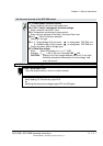
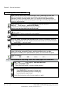
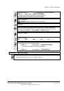
Only for controlled field supply with SDCS-FEX-2 or DCF 503/DCF 504!
505 = 2 Panel display: FEX2 OR FEX3
503 = Rated motor field current
Scales all parameters referenced to the motor field current, such as field cur-
rent limitation or field current monitoring
1305 = Field current for "Under-excitation" signal
Check field current and field voltage by measuring them;
if necessary, correct field current with 503.
3ADW000055R0401_DCS500B_Operating Instruction_e_d