


Chapter 2 - Start-Up Instructions
IV A 2 - 2 DCS 500B / DCP 500B Operating Instructions
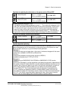
Phase sequence when connecting to the mains / Potential isolation
No special phase sequence required for the main connections U1, V1 and W1!
Phase coordination between electronics section and power section not necessary!
For potential isolation and for avoiding ground loops, an isolating transformer should be
installed upstream when an oscilloscope is being used.
Preventing unintended operating states / Shutting the drive down
CAUTION! As laid down in DIN 57100 Part 727 / VDE 0100 Part 727 (Preventing
unintended operating states), shutting the drive down by means of the
signals at the binary inputs DIx is not sufficient in itself as the sole
measure involved for avoiding unintended operating states or shutting
the drive down in the event of danger!
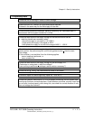
Range of application for the Start-Up Instructions
The Start-Up Instructions are referenced to the parameter settings in their as-delivered
condition (default values) and to the unit wiring as shown in connection diagram 1 or 2
(see Appendix A). In both circuit variants, the binary inputs DI5, DI7 and DI8 can be used.
They will cause the reactions at the drive as described below.
The symbols stated in this context will be repeatedly used further on in the text.
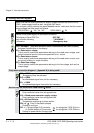
Method of functioning of the binary inputs DI5, DI7 and DI8
• Binary input DI5; designation EM STOP
In operation, DI5 must be set to logical "1“. If it is set to "0“, the alarm signal A 102
will appear. The drive will react in accordance with the function set at Parameter 917
(shutdown with ramp, with torque limit/current limit, with controller blocking and
coasting). Once ramp-down has been completed (speed feedback below n
min
), the
output is reset for controlling the line contactor. After that, the EM STOP input
should be set back to "1“, the alarm message acknowledged, and the ON/OFF input
likewise be set to "0“. After that, the drive can be started anew.
•
Binary input DI7; designation ON/OFF
For connecting the drive to the mains, DI7 must be set to logical "1“. If there are no
ongoing faults, the outputs for controlling the contactors for the armature circuit and
the field circuit will be activated. If DI7 is set to "0“, the controllers will be blocked in-
ternally and the outputs reset after a time-delay.
The function which can be set with Parameter 915 (inputs DI7 and DI8 for switching
the contactors) will only be operative when the drive has been wired as shown
in connection diagram 2.
3ADW000055R0401_DCS500B_Operating Instruction_e_d