


Chapter 2 - Start-Up Instructions
IV A 2 - 24 DCS 500B / DCP 500B Operating Instructions
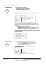
When the display shows NOT ACTIVATED (action correctly completed):
Stop drive
Switch OFF power!
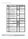
In case the autotuning failed:
1201 = 4 Panel display: ARM. MAN. TUNING
ARM.MAN_TUNING, if the FEX2/3 autotuning failed; activate the reference via pa-
rameter 11209 and set the parameters of the square wave function generator; then
adapt the current controller to get the behaviour shown at curve D chapter 2.6.3 in
this manual
1215 = 4 Panel display: FEXLINK NODE 1
DCF mode FEXLINK NODE1 via FEX-link activated
11202 = SAVE MOT1 SET
Save the altered values in the non-volatile memory!
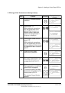
The DCS converter in DCF-mode (parameter 1215=1 or higher) will not accept a start
command, if an alarm or fault is still active (an A or F indication on the 7-segment dis-
play). To ensure a correct function afterwards, please make sure the reasons for any
type of alarm or fault is no longer present.
Continue with Chapter 2.4
3ADW000055R0401_DCS500B_Operating Instruction_e_d