


Chapter 4 - Signals and Troubleshooting
DCS 500B / DCP 500B Operating Instructions
IV A 4 - 15
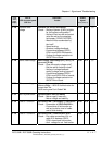
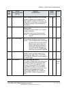
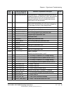
Code
seven
segm.
display
Text on
LCD of control panel
CDP 31x
Definition /
Possible source
Signal
number
(ALARM_WORD_1/2)
Remark
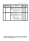
A 134
Backup not allowed
Alarm Change of Parameter Set not allowed
Signal will appear when an attempt has
been made to change from Motor Set 1 to
Motor Set 2 or vice versa, e.g. while the mo-
tor shaft is turning or the line contactor is
switched on.
11105
bit 4
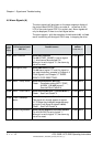
A 136
Write backup alarm
Alarm Write Backup of Values in Non-Volatile
Memory failed
The attempt to save values in non-volatile
memory has failed;
parameter memory could not be erased.
Check: - Is Jumper
S3 enabling the save
routine?
11105
bit 5
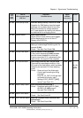
A 137
Arm. current ripple
Armature current ripple
One or several thyristors carry no current.
Check: - Current feedback with oscilloscope
(6 pulses within one cycle visible?)
- Branch fuses, thyristor gate con-
nection; gate-cathode resistance.
- Sensitivity of monitoring function:
set CUR_RIPPLE_LIM [421] (de
pending on the methode; see F34)
11105 bit 9
Can
not be re-
set
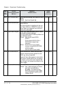
A 138
Init values read
Alarm Initializiation Values read
Default values have been loaded, using
Parameter
[P 11202], Value 3 (FACTORY_
SET_VALUE); signal may only be entered in
the Fault Logger.
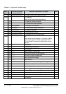
A 140
Auto-reclosing
Auto-Reclosing (Self-Restart)
This alarm indicates when self-restart is per-
formed. During that time the alarms F29,
F31, F39 and F41 are suppressed. This
function is started when the line voltage
drops below the alarm or error threshold,
when not in synchronism, no field or no line
contactor acknowledgement and with
PWR_LOSS_MODE [9.19] = enable and
PWR_DOWN_TIME [5.10] greater than
zero.
11105 bit 8
modified
in
S21.232
3ADW000055R0401_DCS500B_Operating Instruction_e_d