


1-12 Dell OptiPlex GX
pro
Systems Service Manual
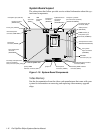
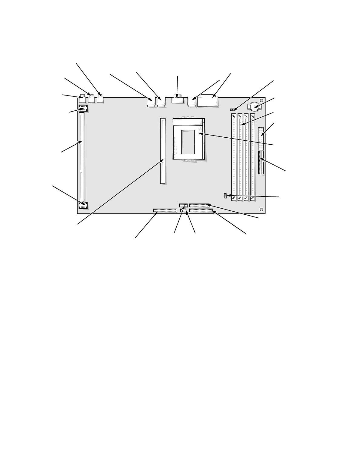
System Board Layout
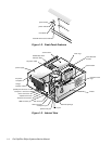
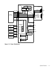
The subsections that follow provide service-related information about the sys-
tem board components.
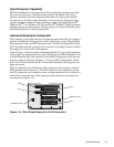
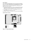
Figure 1-10. System Board Components
Video Memory
See the documentation from the video card manufacturer that came with your
system for information on removing and replacing video-memory upgrade
chips.
serial port 2
connector
(SERIAL2)
serial port 1/parallel
port connectors (stacked)
(PARALLEL/SERIAL)
diskette/tape drive interface
connector (DSKT)
front of system unit
primary EIDE
interface connector (IDE1)
DIMM sockets (4)
microprocessor socket
(MICROPROCESSOR)
riser board
connector (RISER)
battery socket
(BATTERY)
secondary EIDE interface
connector (IDE2)
NIC
connector
(ENET)
jumpers
microprocessor fan
connector (FAN)
speaker-out jack
(SPKR-OUT)
line-in jack (LINE-IN)
microphone jack (NIC-IN)
CD-ROM
connector (CD_IN)
control panel
connector (PANEL)
main power input
connector (POWER1)
3.3-V power
input connectors
(POWER2)
secondary microprocessor
card (or terminator
card) connector (2ND_CPU)
keyboard/mouse
connectors
(stacked)
(KYBD/MOUSE)
riser board power
connector
(RSR PWR2)
riser board power
connector (RSR PWR1)
USB
connector
(USB)