


Removing and Replacing Parts 4-9
D
rives
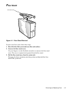
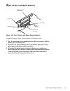
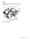
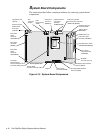
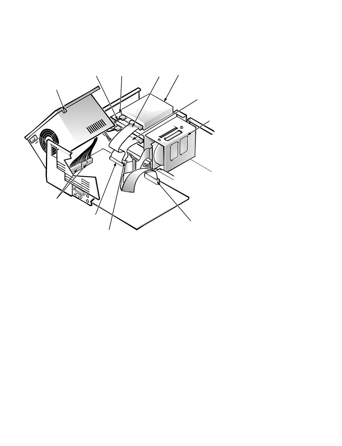
Figure 4-8 shows an example of drive hardware that can be installed in the sys-
tem unit. Refer to this figure when you perform any of the procedures in the
following subsections.
Figure 4-8. Drive Hardware
diskette/tape drive
interface cable
DC power cable
DSKT
connector
system
power supply
two-bay
drive cage
hard-disk
drive bracket
IDE1
connector
IDE2 connector
3.5-inch diskette
drive
CD-ROM/tape drive
interface cable
power input
connectors