


vii
Terminator Card . . . . . . . . . . . . . . . . . . . . . . . . . . . . . . . . . . . . . . . . 4-23
Add-In Card . . . . . . . . . . . . . . . . . . . . . . . . . . . . . . . . . . . . . . . . . . . 4-24
System Battery . . . . . . . . . . . . . . . . . . . . . . . . . . . . . . . . . . . . . . . . . . . . 4-25
System Board . . . . . . . . . . . . . . . . . . . . . . . . . . . . . . . . . . . . . . . . . . . . . . . . 4-26
Appendix A
System Setup Program . . . . . . . . . . . . . . . . . . . . . . . . . . A-1
System Setup Screens . . . . . . . . . . . . . . . . . . . . . . . . . . . . . . . . . . . . . . . . . . .A-2
Index
Figures
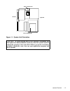
Figure 1-1. System Unit Orientation. . . . . . . . . . . . . . . . . . . . . . . . . . . . . . 1-3
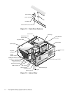
Figure 1-2. Front-Panel Features . . . . . . . . . . . . . . . . . . . . . . . . . . . . . . . . 1-4
Figure 1-3. Internal View . . . . . . . . . . . . . . . . . . . . . . . . . . . . . . . . . . . . . . 1-4
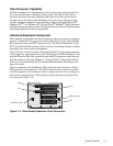
Figure 1-4. Riser-Board Expansion-Card Connectors . . . . . . . . . . . . . . . . 1-5
Figure 1-5. DC Power Connector P1 . . . . . . . . . . . . . . . . . . . . . . . . . . . . . 1-9
Figure 1-6. DC Power Connectors P2, P3, P4, P5, and P6. . . . . . . . . . . . . 1-9
Figure 1-7. DC Power Connectors P7 . . . . . . . . . . . . . . . . . . . . . . . . . . . 1-10
Figure 1-8. DC Power Cables. . . . . . . . . . . . . . . . . . . . . . . . . . . . . . . . . . 1-10
Figure 1-9. Power Distribution . . . . . . . . . . . . . . . . . . . . . . . . . . . . . . . . . 1-11
Figure 1-10. System Board Components . . . . . . . . . . . . . . . . . . . . . . . . . . 1-12
Figure 1-11. System Board Jumpers. . . . . . . . . . . . . . . . . . . . . . . . . . . . . . 1-13
Figure 4-1. Floor Stand Removal . . . . . . . . . . . . . . . . . . . . . . . . . . . . . . . . 4-3
Figure 4-2. System-Unit Cover Removal . . . . . . . . . . . . . . . . . . . . . . . . . . 4-4
Figure 4-3. Padlock Removal . . . . . . . . . . . . . . . . . . . . . . . . . . . . . . . . . . . 4-4
Figure 4-4. Eject, Power, and Reset Button Removal . . . . . . . . . . . . . . . . 4-5
Figure 4-5. Front-Panel Insert Removal . . . . . . . . . . . . . . . . . . . . . . . . . . . 4-6
Figure 4-6. Indicator Card Removal. . . . . . . . . . . . . . . . . . . . . . . . . . . . . . 4-7
Figure 4-7. Speaker Removal . . . . . . . . . . . . . . . . . . . . . . . . . . . . . . . . . . . 4-8
Figure 4-8. Drive Hardware . . . . . . . . . . . . . . . . . . . . . . . . . . . . . . . . . . . . 4-9
Figure 4-9. 3.5-Inch Diskette Drive Removal . . . . . . . . . . . . . . . . . . . . . 4-10
Figure 4-10. 5.25-Inch Drive Removal. . . . . . . . . . . . . . . . . . . . . . . . . . . . 4-11
Figure 4-11. Hard-Disk Drive Bracket Removal . . . . . . . . . . . . . . . . . . . . 4-12
Figure 4-12. Hard-Disk Drive Removal . . . . . . . . . . . . . . . . . . . . . . . . . . . 4-13
Figure 4-13. Power Supply Removal . . . . . . . . . . . . . . . . . . . . . . . . . . . . . 4-14
Figure 4-14. Microprocessor Fan Removal . . . . . . . . . . . . . . . . . . . . . . . . 4-15
Figure 4-15. System Board Components . . . . . . . . . . . . . . . . . . . . . . . . . . 4-16