


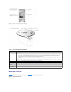
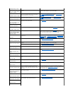
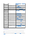

Table 2-2. Back-PanelFeatures
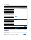
Power Indicator Codes
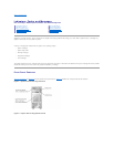
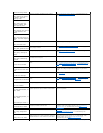
The power button on the front panel controls the power input to the system's power supplies. The power indicator can provide information on power status
(see Figure2-3). Table2-3 lists the power button indicator codes.
Table 2-3. Power Button Indicators
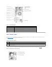
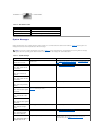
The indicators on the optional redundant power supplies show whether power is present or whether a power fault has occurred (see Figure2-5).
Figure 2-5. Redundant Power Supply Indicators
Component
Description
Power connector
Connects the system's power supply to a power source.
Power cable strain relief loop
Relieves strain on the power cable.
NIC indicators
Provide information on NIC status (see "NIC Indicator Codes").
Expansion slots
Provide two 64-bit/100-MHz slots, two 64-bit/66-MHz slots, and two 32-bit/33-MHz slots.
I/O ports and connectors
Connect peripheral devices to the system.
Indicator
Function
On
Indicates that power is supplied to the system and the system is operational.
Off
Indicates that no power is supplied to the system.
Blinking
Indicates that power is supplied to the system, but the system is in a standby state. For information on standby states, see your operating
system documentation.