


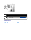
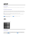
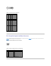
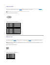

Table A-1.SystemBoardJumperSettings
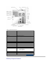
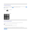
System Board Connectors
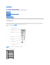
See FigureA-3 and TableA-2 for the location and description of system board connectors. FigureA-3 also indicates expansion slots and bus operating speeds.
Figure A-3. System Board Connectors
Jumper
Setting
Description
J11 pins 1 and
2
(default)
The password feature is enabled.
The password feature is disabled.
J11 pins 3 and
4
(default)
The configuration settings in NVRAM are retained at system boot.
The configuration settings in NVRAM are cleared at next system boot (see "Resetting Corrupted BIOS Configuration" in
"Troubleshooting Your System").
jumpered unjumpered