


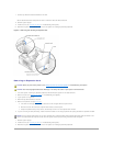

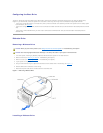
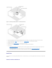

The 3.5-inch diskette drive, 5.25-inch devices, and non-hot-plug hard drives must connect to a DC power cable from the system power supply. (Hot-plug SCSI
drives obtain their power from the optional SCSI backplane.)
IDE Configuration Information
The IDE subsystem provides two channels (primary and secondary). Each channel can support up to two IDE drives such as high-capacity hard drives, CD
drives, DVD drives, and tape drives.
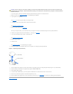
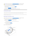
Each IDE drive should be configured for the Cable Select setting, which assigns master and slave status to a drive according to its position on the interface
cable. In this configuration, the drive attached to the last connector on the interface cable is the master or boot drive (drive 0) and the drive attached to the
middle connector on the interface cable is the slave drive (drive 1). See the drive's documentation for instructions on configuring the Cable Select setting.
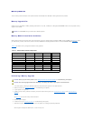
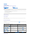
Table7-2 lists guidelines for installing IDE drives connected to the IDE system board connectors.
Table 7-2. IDE Drive Configuration Guidelines
SCSI Configuration Information
Although SCSI drives are installed in essentially the same way as other drives, their configuration requirements are different. To install and configure a SCSI
drive, follow the guidelines in the following subsections.
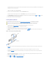
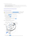
SCSI Interface Cables
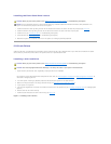
SCSI interface connectors are keyed for correct insertion. Keying ensures that the pin-1 wire in the cable connects to pin 1 in the connectors on both ends.
When you disconnect an interface cable, take care to grasp the cable connector, rather than the cable itself, to avoid stress on the cable.
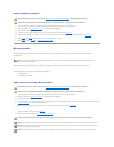
SCSI ID Numbers
EachdriveattachedtoaSCSIcontrollermusthaveauniqueSCSIIDnumberfrom0to15.
l The SCSI hard drive from which the system boots is configured as SCSI ID 0.
l A SCSI tape drive is typically configured as SCSI ID 6.
l If you install optional SCSI drives or change your SCSI configuration, see the documentation for each SCSI drive for information on setting the
appropriate SCSI ID number.
Device Termination
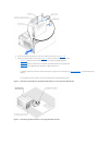
SCSI logic requires that termination be enabled for the two drives at opposite ends of the SCSI chain and disabled for all drives in between. For internal SCSI
drives, termination is configured automatically. See the documentation provided with any optional SCSI drive you purchase for information on disabling
termination.
IDE Channel
System Board Connector
Drive Type(s)
1
PRIMARY IDE
IDE hard drives
2
SECONDARY IDE
IDE CD, DVD, tape, or combination drives
NOTE: The configurations shown in this table describe IDE drives connected directly to the IDE system board connectors. To identify system board
connectors, see FigureA-3.
NOTE: There is no requirement that SCSI ID numbers be assigned sequentially or that drives be attached to the cable in order by ID number.