


Removing Memory Modules
1. Turn off the system, including any attached peripherals, and disconnect the system from the electrical outlet.
2. Remove the cover (see "Removing the Cover" in "Troubleshooting Your System").
3. Lay the system on its right side.
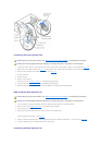
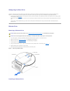
4. Locate the memory module connectors from which you will remove memory modules (see FigureA-3).
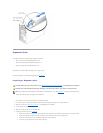
5. Press down and outward on the memory module connector ejectors until the memory module pops out of the connector (see Figure6-4).
6. Repeat step4 and step5 of this procedure to remove any other memory modules.
7. Perform step5 through step10 of "Performing a Memory Upgrade."
Microprocessors
To take advantage of future options in speed and functionality, you can add a second microprocessor or replace either the primary or secondary
microprocessor.
Each microprocessor and its associated cache memory are contained in a PGA package that is installed in a ZIF socket on the system board.
The following items are included in the microprocessor upgrade kit:
l A microprocessor
l A heat sink with cooling fan
Removing and Installing a Microprocessor
1. Turn off the system, including any attached peripherals, and disconnect the system from the electrical outlet.
2. Remove the cover (see "Removing the Cover" in "Troubleshooting Your System").
3. Lay the system on its right side.
4. If you are removing or installing a microprocessor in socket CPU2, remove the vertical plastic baffle to improve access to the microprocessor socket (see
"Removing the Baffle" in "Troubleshooting Your System").
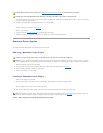
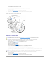
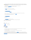
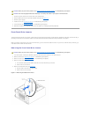
5. Disconnect the microprocessor fan cable from the fan power connector on the system board (see Figure6-5).
To identify system board connectors, see FigureA-3.
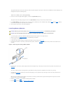
6. Remove the back system fan (see "Removing the Back System Fan").
CAUTION: Before you perform this procedure, see "Safety First—For You and Your System" in "Troubleshooting Your System."
CAUTION: See "Protecting Against Electrostatic Discharge" in the safety instructions in your System Information Guide.
NOTE: The second microprocessor must be of the same type as the first. If the two microprocessors are different speeds, both will operate at the
speed of the slower microprocessor.
CAUTION: Before you perform this procedure, see "Safety First—For You and Your System" in "Troubleshooting Your System."
CAUTION: See "Protecting Against Electrostatic Discharge" in the safety instructions in your System Information Guide.
CAUTION: The microprocessor and heat sink can become extremely hot. Be sure they have had sufficient time to cool before handling.
NOTICE: Do not operate the system without the fan and heat sink assembly installed. The assembly is required to maintain proper thermal conditions.
NOTICE: After removing the fan and heat sink assembly, place it upside down on a flat surface to prevent the thermal interface material on the heat
sink from being damaged or contaminated.
NOTICE: The microprocessor fan and heat sink are constructed together as a single assembly. Do not attempt to remove the fan from the heat sink.