


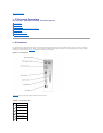
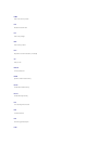

Video Connector
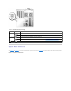
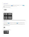
You can attach a VGA-compatible monitor to the system's integrated video controller using a 15-pin high-density D-subminiature connector. FigureB-5
illustrates the pin numbers for the video connector and TableB-5 defines the pin assignments for the connector.
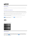
Figure B-5. Video Connector Pin Numbers
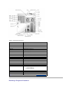
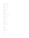
Table B-5. Video Connector Pin Assignments
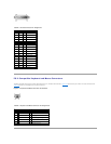
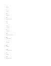
USB Connector
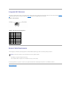
The system's USB connector supports USB-compliant peripherals such as keyboards, mice, and printers and may also support USB-compliant devices such as
diskette drives and CD drives. FigureB-6 illustrates the pin numbers for the USB connector and TableB-6 defines the pin assignments for the connector.
Figure B-6. USB Connector Pin Numbers
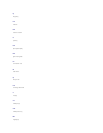
Table B-6. USB Connector Pin Assignments
NOTE: Installing a video card automatically disables the system's integrated video controller.
Pin
Signal
I/O
Definition
1
RED
O
Red video
2
GREEN
O
Green video
3
BLUE
O
Blue video
4
NC
N/A
No connection
5–8, 10
GND
N/A
Signal ground
9
VCC
N/A
Vcc
11
NC
N/A
No connection
12
DDC data out
O
Monitor detect data
13
HSYNC
O
Horizontal synchronization
14
VSYNC
O
Vertical synchronization
15
NC
N/A
No connection
NOTICE: Do not attach a USB device or a combination of USB devices that draw a maximum current of more than 500 mA per channel or +5 V. Attaching
devices that exceed this threshold may cause the USB connectors to shut down. See the documentation that accompanied the USB devices for their
maximum current ratings.
Pin
Signal
I/O
Definition
1
Vcc
N/A
Supply voltage
2
DATA
I
Data in
3
+DATA
O
Data out
4
GND
N/A
Signal ground