


Installing System Components 137
11
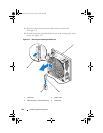
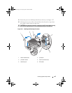
Rotate the processor shield upward and out of the way. See Figure 3-23.
12
Lift the processor out of the socket and leave the release lever up so that
the socket is ready for the new processor.
CAUTION: Be careful not to bend any of the pins on the ZIF socket when removing
the processor. Bending the pins can permanently damage the system board.
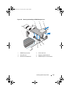
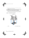
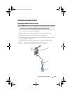
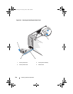
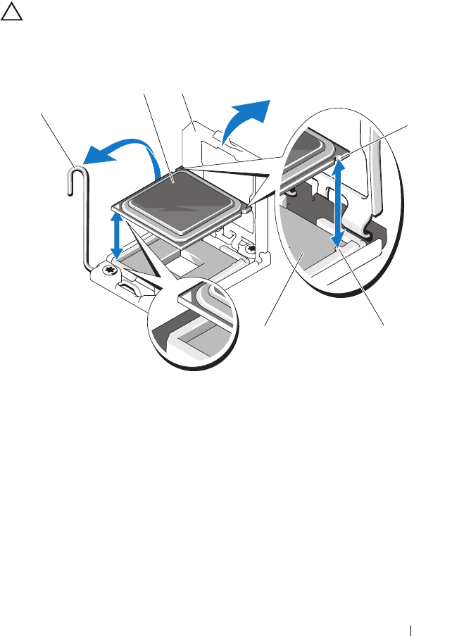
Figure 3-23. Installing and Removing a Processor
1 socket-release lever 2 processor
3 processor shield 4 notch in processor (2)
5 socket key (2) 6 ZIF socket
2
6
1
3
5
4
book.book Page 137 Tuesday, June 9, 2009 4:09 PM