


24-port NWay Ethernet Switch User’s Guide
Identifying External Components 7
3
IDENTIFYING EXTERNAL COMPONENTS
This chapter describes the front panel, rear panel, optional plug-in modules, and LED indicators of the DES-3225G.
Front Panel
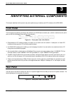
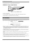
The front panel of the Switch consists of LED indicators, an RS-232 communication port, a slide-in module slot, two uplink
ports, and 22 (10/100 Mbps) Ethernet/Fast Ethernet ports.
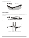
Figure 3-1. Front panel view of the Switch
♦ Comprehensive LED indicators display the status of the switch and the network. A description of these LED
indicators follows (see the LED Indicators section below).
♦ An RS-232 DCE console port for setting up and managing the switch via a connection to a console terminal or PC
using a terminal emulation program.
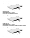
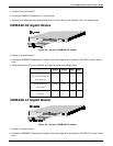
♦ A front-panel slide-in module slot for 10/100 Mbps Ethernet ports can accommodate a 2-port 10/100BASE-TX Fast
Ethernet module, a 2-port 100BASE-FX MT-RJ type module, or a 1-port 100BASE-FX SC type module.
♦ Two MDI-II Uplink jacks which can be used to connect a straight-through cable to a normal (non-Uplink) port on a
switch or hub. Do not use port 1X if the top Uplink port is occupied or Port 2X if the bottom Uplink port is occupied.
♦ Twenty-two high-performance, NWay Ethernet ports all of which operate at 10/100 Mbps for connections to end
stations, servers and hubs. All ports can auto-negotiate between 10Mbps or 100Mbps, full- or half-duplex, and flow
control.
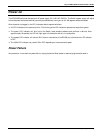
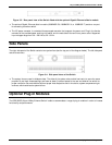
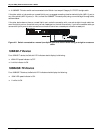
Rear Panel
The rear panel of the switch consists of a slot for an optional Gigabit Ethernet fiber port and an AC power connector. The
following displays the rear panel of the switch.
Figure 3-2. Rear panel view of the Switch