


24-port NWay Ethernet Switch User’s Guide
Identifying External Components 11
♦ Allows connections up to 5 km in length using single-mode fiber optic cable.
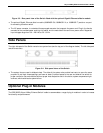
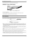
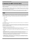
1000BASE-T Copper Gigabit Module
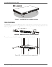
Figure 3-10. One-port, 1000BASE-T module
♦ One-port, rear-panel module.
♦ Connects to 1000BASE-T devices at 1000M/full duplex, 100M/full duplex, 100M/half duplex, and Auto.
♦ Supports Category 5+ or higher cable connections of up to 100 meters.
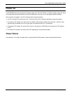
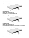
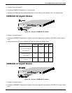
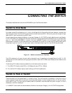
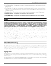
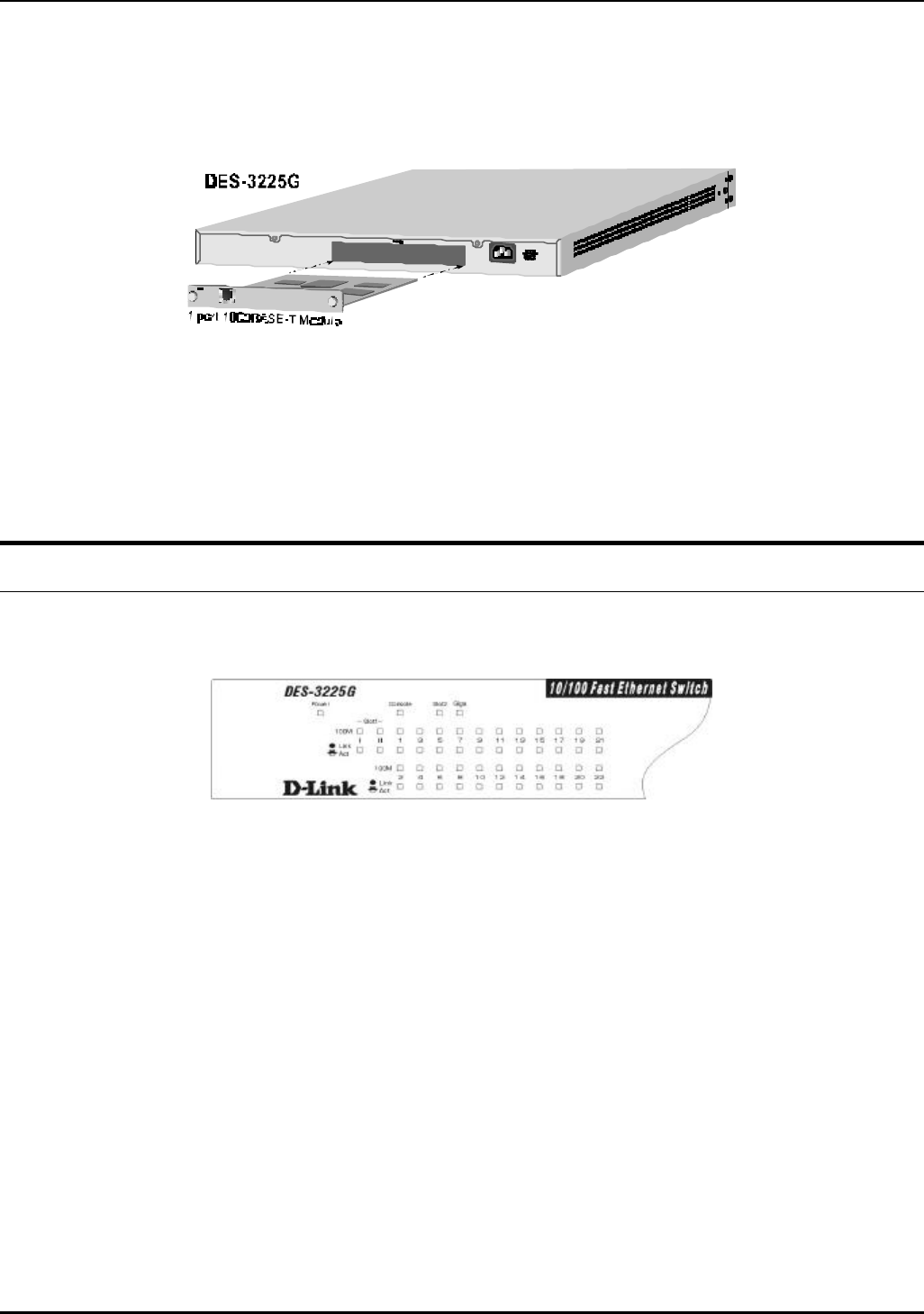
LED Indicators
The LED indicators of the Switch include Power, Console, Slot2, Giga, Speed, and Link/Act. The following shows the LED
indicators for the Switch along with an explanation of each indicator.
Figure 3-11. The LED indicators
♦ Power This indicator on the front panel should be colored amber during the Power-On Self Test (POST). It will
light green approximately 2 seconds after the switch is powered on to indicate the ready state of the device. The LED
will blink green while downloading new software for the switch, or if the system’s configuration has changed and will
light yellow when an error occurs.
♦ Console This indicator is lit green when the switch is being managed via out-of-band/local console management
through the RS-232 console port using a straight-through serial cable.
♦ Slot 2 This indicator is lit green when a Gigabit Ethernet slide-in module is present in the rear panel of the
Switch.
♦ Giga This indicator is lit green when a link is established. It blinks green when the Gigabit port is active.
♦ 100M These indicators are illuminated green when a 100 Mbps device is connected to any of the 24 ports or uplink
port. If a 10 Mbps device is connected to any of the 24 ports or uplink port, these LEDs remain dark.
♦ Link/Act These indicators are lit when there is a secure connection (or link) to a device at any of the ports. The
LEDs blink whenever there is reception or transmission (i.e. Activity--Act) of data occurring at a port.