


24-port NWay Ethernet Switch User’s Guide
Switch Management Concepts 23
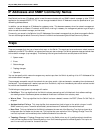
Sharing Resources Across 802.1Q VLANs
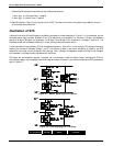
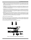
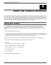
Network resources such as printers and servers however, can be shared across 802.1Q VLANs. This is achieved by setting
up overlapping VLANs as shown in the diagram below.
VLAN 1
Po rt
VID s = 1
VLAN 2
Po rt
VI Ds = 2
Po rt
PV ID = 3
V
L
A
N
3
1 2 3 4 5 6 7 8 9 1 0 1 1 12
Graphics
Workstations
Workstations
Network
S
e
r
v
e
r
Figure 5-4. Example of typical VLAN configuration
In the above example, there are three different 802.1Q VLANs and each port can transmit packets on one of them
according to their Port VLAN ID (PVID). However, a port can receive packets on all VLANs (VID) that it belongs to. The
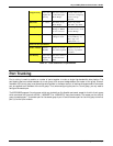
assignments are as follows:
PVID
(Port VLAN
ID)
Ports
1 Port 1
1 Port 2
1 Port 3
2 Port 11
2 Port 12
3 Port 7
VID
(VLAN ID)
Member
Ports
1 1,2,3,7
2 7,11,12
3 1,2,3,7,11,12
Table 5-2. VLAN assignments for Figure 5-4
The server attached to Port 7 is shared by VLAN 1 and VLAN 2 because Port 7 is a member of both VLANs (it is listed as
a member of VID 1 and 2). Since it can receive packets from both VLANs, all ports can successfully send packets to it.
Ports 1, 2 and 3 send these packets on VLAN 1 (their PVID=1), and Ports 11 and 12 send these packets on VLAN 2
(PVID=2). The third VLAN (PVID=3) is used by the server to transmit files that had been requested on VLAN 1 or 2 back
to the computers. All computers that use the server will receive transmissions from it since they are all located on ports
which are members of VLAN 3 (VID=3).
802.1Q VLANs Spanning Multiple Switches
802.1Q VLANs can span multiple switches as well as your entire network. Two considerations to keep in mind while
building VLANs of this sort are whether the switches are IEEE 802.1Q-compliant and whether VLAN packets should be
tagged or untagged.
Definitions of relevant terms are as follows: