


Programming Details
MVME3100 Single Board Computer Installation and Use (6806800M28C)
130
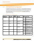
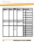
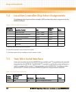
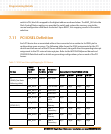
7.4 Local Bus Controller Chip Select Assignments
The following table shows local bus controller (LBC) bank and chip select assignments for the
MVME3100 board.
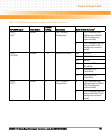
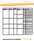
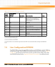
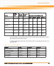
7.5 Two-Wire Serial Interface
A two-wire serial interface for the MVME3100 is provided by an I
2
C compatible serial controller
integrated into the MPC8540. The MPC8540 I
2
C controller is used by the system software to
read the contents of the various I
2
C devices located on the MVME3100. The following table
contains the I
2
C devices used for the MVME3100 and their assigned device addresses.
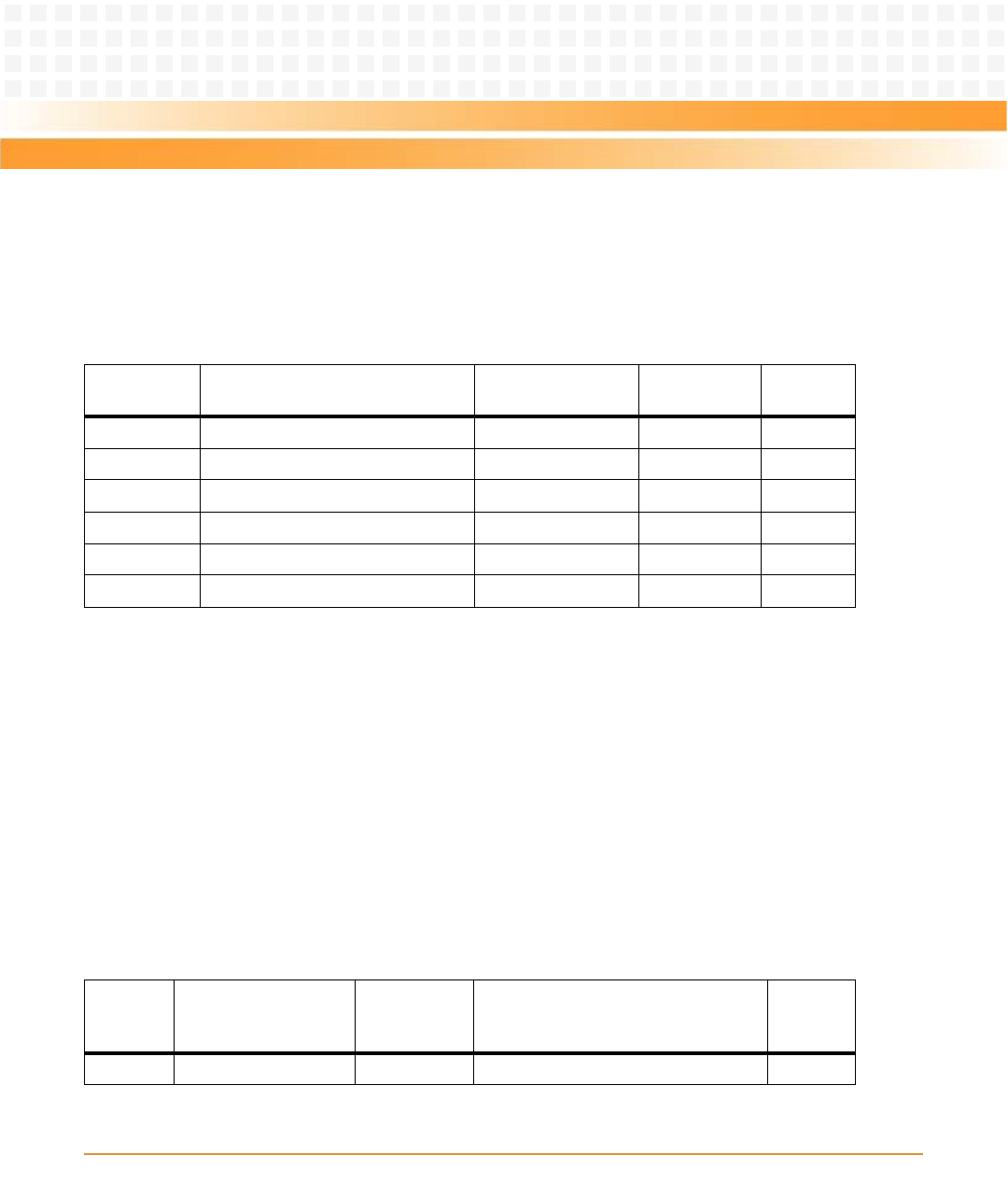
Table 7-3 LBC Chip Select Assignments
LBC Bank/
Chip Select Local Bus Function Size
Data Bus
Width Notes
0 Boot Flash bank 32MB - 128MB 32 bits
1
1 Optional second Flash bank 32MB - 128MB 32 bits
1
2 Control/Status registers 64 KB 32 bits
2
3 Quad UART 64 KB 8 bits
4 32-bit timers 64 KB 32 bits
3
5-7 Not used
1. Flash bank size determined by VPD flash packet.
2. Contro/Status registers are byte read and write capable.
3. 32-bit timer registers are byte readable, but must be written as 32 bits.
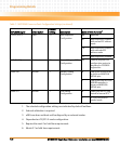
Table 7-4 I2C Bus Device Addressing
I2C Bus
Address
Device Address
A2 A1 A0
(binary) Size (bytes) Device Function Notes
$90 000 N/A DS1621 temperature sensor