


Functional Description
MVME3100 Single Board Computer Installation and Use (6806800M28C)
80
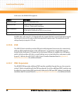
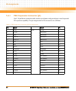
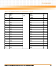
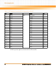
In this case, the MVME3100 supports:
On PMC site 1, the user I/O — J14 signals will only support the low-current, high-speed signals
and are not to be used for any current bearing power supply usage. The maximum current
rating of each pin/signal is 100 mA.
4.10.6 USB
The USB 2.0 host controller provides USB ports with integrated transceivers for connectivity
with any USB-compliant device or hub. USB channel 1 is routed to a single USB connector
located at the front panel. DC power to the front panel USB port is supplied via a USB power
switch, which provides soft-start, current limiting, over-current detection, and power enable
for port 1. Refer to the μPD720101 USB 2.0 Host Controller Datasheet listed in Appendix B,
Related Documentation, for additional details.
4.10.7 PMC Expansion
The MVM3E3100 provides additional PMC module capability through the use of a connector
on bus C that is compatible with the PMCspan boards. Up to four additional PMC modules may
be added by using existing PMCspan boards. Refer to the PMCspan PMC Adapter Carrier Board
Installation and Use manual listed in Appendix B, Related Documentation, for additional details.
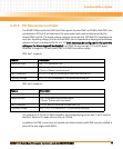
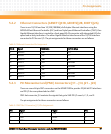
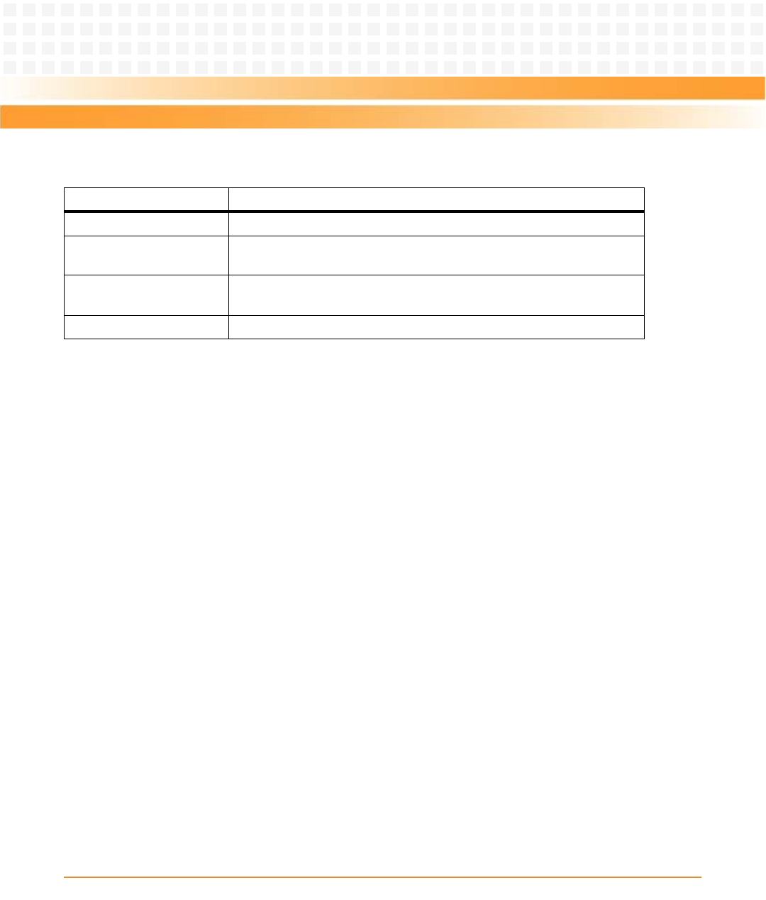
Feature Description
Mezzanine Type: PMC = PCI Mezzanine Card
Mezzanine Size: Double width and standard depth
(150mm x 150mm) with front panel
PMC Connectors: J11, J12, J13, J14, J21, J22, and J23
(32/64-bit PCI with front and rear I/O) on J14 only
Signaling Voltage: VIO = +3.3V (+5V tolerant) or +5V, selected by keying pin