


Startup and Operation
MVME3100 Single Board Computer Installation and Use (6806800M28C)
38
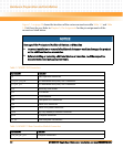
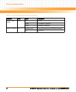
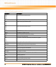
The MVME721 rear transition module also has four status indicators. The following table
describes these indicators:
Table 2-2 MVME721 LED Status Indicators
Function Label Color Description
GENET 2 Link/Speed SPEED Off No link
Yellow 10/100Base-T operation
Green 1000Base-T operation
GENET 2 Activity ACT Blinking Green Activity proportional to bandwidth utilization.
Off No activity
ENET 1 Link/Speed SPEED Off No link
Yellow 10/100Base-T operation
ENET 1 Activity ACT Blinking Green Activity proportional to bandwidth utilization.
Off No activity
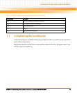
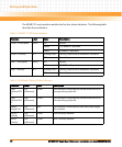
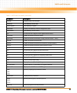
Table 2-3 Additional Onboard Status Indicators
Function Label Color Description
User
Defined LED
2
DS7
(silkscreen)
Green This indicator is illuminated by software assertion of its
corresponding register bit.
User
Defined LED
3
DS8
(silkscreen)
Green This indicator is illuminated by software assertion of its
corresponding register bit.
Power
Supply Fail
DS1
(silkscreen)
Red This indicator is illuminated to indicate a power supply
fail condition.
sATA 0
Activity
DS4
(silkscreen)
Green sATA 0 activity indicator
sATA 1
Activity
DS5
(silkscreen)
Green sATA 1 activity indicator