Hardware Preparation and Installation
MVME3100 Single Board Computer Installation and Use (6806800M28C)
32
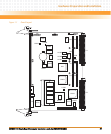
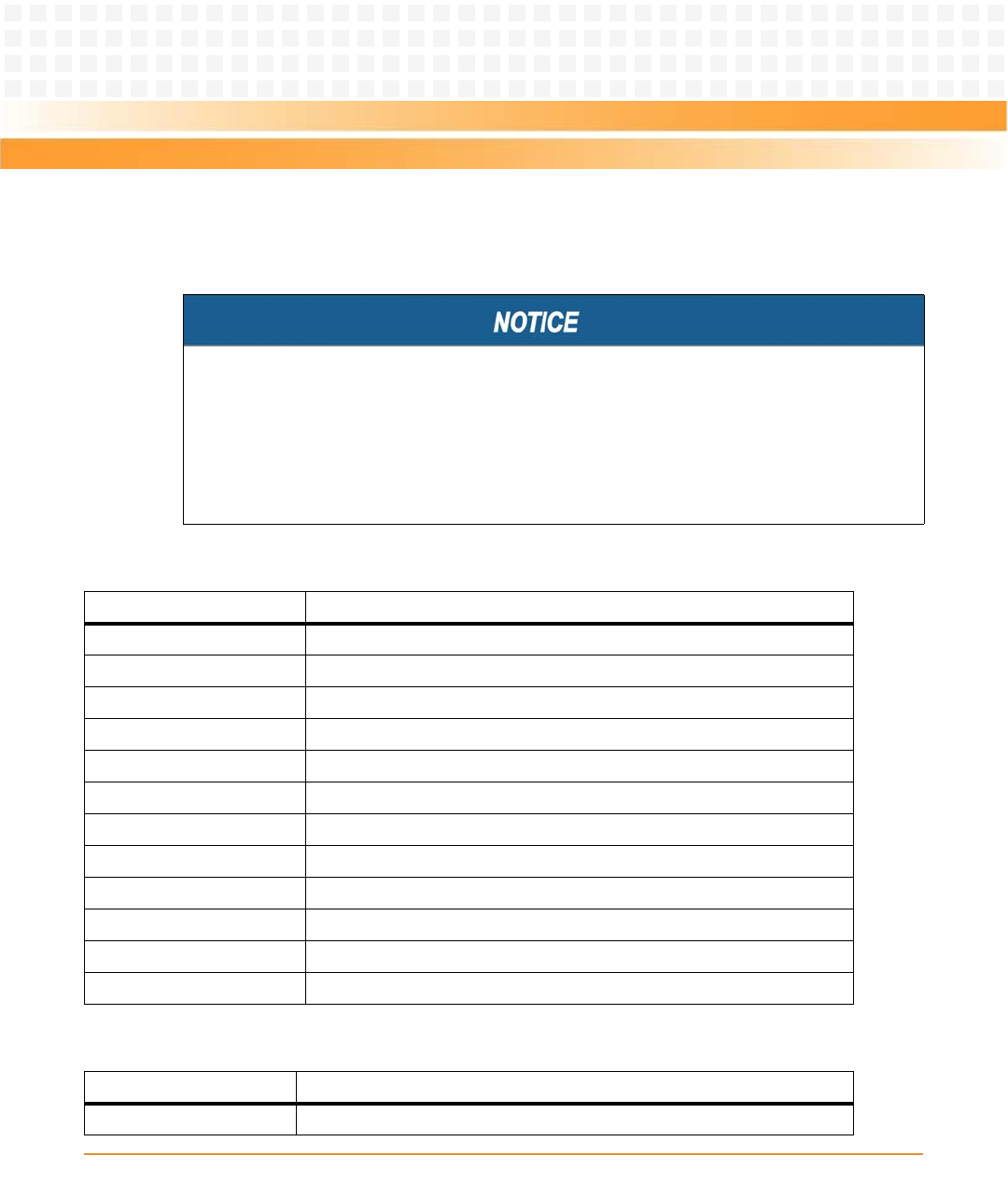
Figure 1-1 on page 25 shows the locations of the various connectors while Table 1-7 and Table
1-8 list them for you. Refer to Chapter 5, Pin Assignments for the pin assignments of the
connectors listed below.
Damage of the Product and Additional Devices and Modules
z Incorrect installation or removal of additional devices or modules damages the product
or the additional devices or modules.
z Before installing or removing additional devices or modules, read the respective
documentation and use appropriate tools.
Table 1-7 MVME3100 Connectors
Connector Function
J4 PMC expansion connector
J11, J12, J13, J14 PCI mezzanine card (PMC) slot 1 connector
J21, J22, J23 PCI mezzanine card (PMC) slot 2 connector
J24 Boundary scan header
J25 COP header
J27 USB connector
J28 Front panel sATA connector
J29 Planar sATA connector
J30 Planar sATA power connector
J41B 10/100/1000Mb/s Ethernet connector
J41A COM port connector
P1, P2 VME backplane connectors
Table 1-8 MVME721 Rear Transition Module Connectors
Connector Function
J1A, J1B, J1C, J1D COM port connectors


