MOTLoad Firmware
MVME3100 Single Board Computer Installation and Use (6806800M28C)
55
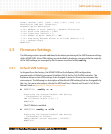
Outbound Image 7 Translation Offset Upper Register = 00000000
Outbound Image 7 Translation Offset Lower Register = 4F000000
Outbound Image 7 2eSST Broadcast Select Register = 00000000
MVME3100>
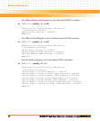
Outbound window 7 (OTAT7) is enabled, 2eSST timing at SST320, transfer mode of SCT,
CR/CSR Supervisory access. The window accepts transfers on the PCI-X Local Bus from
0xB1000000-0xB1FF0000 and translates them onto the VMEbus using an offset of
0x4F000000, thus an access to 0xB1000000 on the PCI-X Local Bus becomes an access to
0x00000000 on the VMEbus.
3.5.2 Control Register/Control Status Register Settings
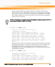
The CR/CSR base address is initialized to the appropriate setting based on the Geographical
address; that is, the VME slot number. See the VME64 Specification and the VME64 Extensions
for details. As a result, a 512K byte CR/CSR area can be accessed from the VMEbus using the
CR/CSR AM code.
3.5.3 Displaying VME Settings
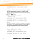
To display the changeable VME setting, type the following at the firmware prompt:
z vmeCfg –s –m
Displays Master Enable state
z vmeCfg –s –i(0 - 7)
Displays selected Inbound Window state
z vmeCfg –s –o(0 - 7)
Displays selected Outbound Window state
z vmeCfg –s –r184
Displays PCI Miscellaneous Register state
z vmeCfg –s –r188
Displays Special PCI Target Image Register state
z vmeCfg –s –r400
Displays Master Control Register state
z vmeCfg –s –r404
Displays Miscellaneous Control Register state


