


SMT Configuration Switch, S1 Hardware Preparation and Installation
MVME7100 Single Board Computer Installation and Use (6806800E08A)
37
The following sections describe the on-board switches and their configurations for the
MVME7100.
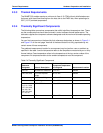
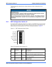
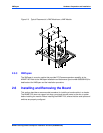
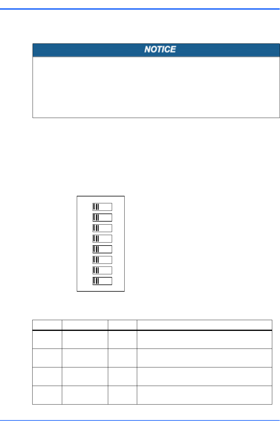
2.4.1 SMT Configuration Switch, S1
An 8-position SMT configuration switch (S1) is located on the MVME7100 to control the flash
bank write-protect, select the flash boot image, and control the safe start ENV settings. The
default setting on all switch positions is OFF and is indicated by brackets in Table 2-5.
Board Malfunction
Switches marked as “reserved” might carry production-related functions and can
cause the board to malfunction if their setting is changed.
Do not change settings of switches marked as “reserved”. The setting of switches
which are not marked as “reserved” has to be checked and changed before board
installation.
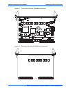
Figure 2-4 SMT Configuration Switch Position
Table 2-5 Configuration Switch Settings (S1)
Switch Description Setting Function
S1-1 Safe Start
1
[OFF]
ON
Use normal ENV
Use safe ENV
S1-2 Boot Block B
Select
[OFF]
ON
Flash memory map normal and boot block A selected
Boot block B selected, mapped to highest address
S1-3 Flash Bank WP [OFF]
ON
Entire flash not write-protected
Flash is write-protected
S1-4 JTAG Pass Thru [OFF]
ON
Normal operation
Pass-Thru mode
1
ON
1
2
3
4
5
6
7
8
Normal ENV
Boot Block A
WP Disabled
Normal Operation
PMC 133 MHz
Reserved
Master WP
Normal Operation