


MVME7100 Single Board Computer Installation and Use (6806800E08A)
Hardware Preparation and Installation Power Requirements
32
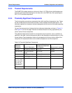
2.3.2 Power Requirements
The MVME7100 uses only +5.0 V from the VMEbus backplane. On board power supplies
generate the required voltages for the various ICs. The MVME 7100 connects the +12 V and -
12 V supplies from the backplane to the PMC sites while the +3.3 V power supplied to the PMC
sites comes from the +5.0 V backplane power. A maximum of 10 A of +3.3 V power is available
to the PMC sites, however the 90 W +5.0 V limit must be observed as well as any cooling
limitations.
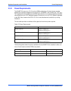
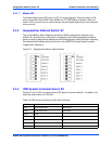
The next table provides an estimate of the typical and maximum power required.
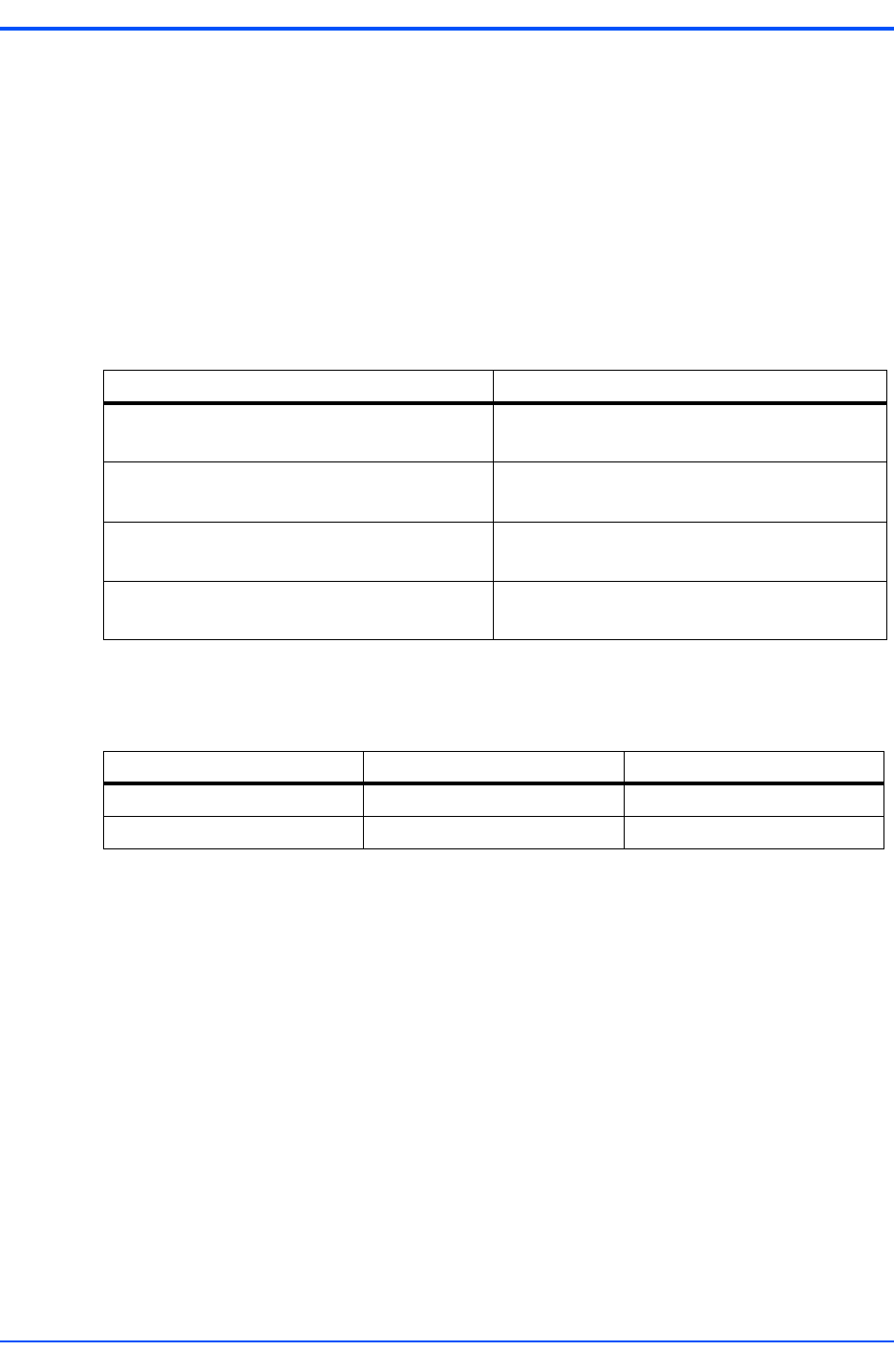
The following table shows the power available when the MVME7100 is installed in either a 3-
row or 5-row chassis and when PMCs are present.
Table 2-3 Power Requirements
Board Variant Power
MVME7100-0161 Typical: 40 W @ +5 V
Maximum: 55 W @ +5 V
MVME7100-0163 Typical: 40 W @ +5 V
Maximum: 55 W @ +5 V
MVME7100-0171 Typical: 45 W @ +5 V
Maximum: 60 W @ +5 V
MVME7100-0173 Typical: 45 W @ +5 V
Maximum: 60 W @ +5 V
Chassis Type Available Power Power With PMCs
3-Row 70 W maximum Below 70 W
1
1. Keep below power limit. Cooling limitations must be considered.
5-Row 90 W maximum Below 90 W
1