MVME7100 Single Board Computer Installation and Use (6806800E08A)
Controls, LEDs, and Connectors Headers
64
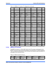
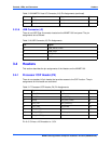
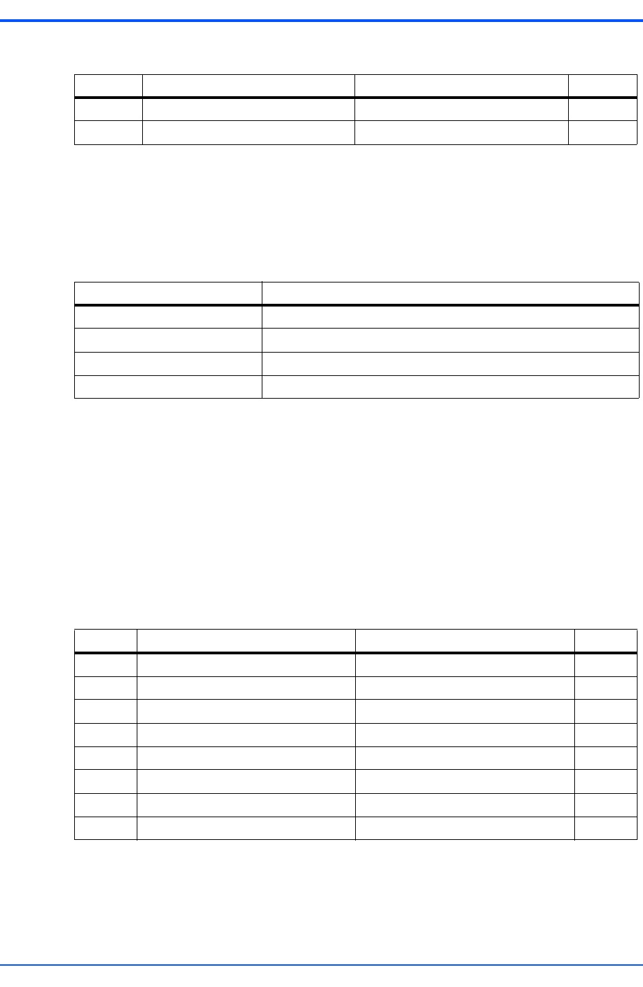
3.3.3.8 USB Connector (J2)
There is one USB Type A connector located on the MVME7100 front panel. The pin
assignments are as follows:
3.4 Headers
This section describes the pin assignments of the Headers on the MVME7100.
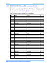
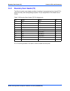
3.4.1 Processor COP Header (P4)
There is one standard 16-pin header that provides access to the COP function. The pin
assignments for this header are as follows:
Pin 6 +3.3V has a 100 Ω resistor to +3.3V.
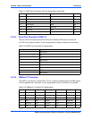
61 No Connect No Connect 62
63 No Connect No Connect 64
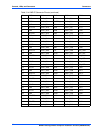
Table 3-15 MVME721 Host I/O Connector (J10) Pin Assignments (continued)
Pin Signal Signal Pin
Table 3-16 USB Connector (J2) Pin Assignments
Pin Signal
1 USB_VBUS (+5.0V)
2 USB_DATA-
3 USB_DATA+
4GND
Table 3-17 Processor COP Header (P4) Pin Assignments
Pin Signal Signal Pin
1 CPU_TDO No Connect 2
3 CPU_TDI CPU_TRST_L 4
5 Pullup CPU_VIO (+3.3V) 6
7 CPU_TCK CPU_CKSTPI_L 8
9 CPU_TMS No Connect 10
11 CPU_SRST_L GND 12
13 CPU_HRST_L KEY (no pin) 14
15 CPU_CKSTPO_L GND 16


