Alternate Boot Data Structure MOTLoad Firmware
MVME7100 Single Board Computer Installation and Use (6806800E08A)
97
6.7.4 Alternate Boot Data Structure
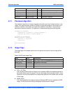
The globalData field of the alternate boot data structure points to an area of RAM which was
initialized to zeroes by the boot loader. This area of RAM is not cleared by the boot loader after
execution of a POST image, or other alternate boot image, is executed. It is intended to provide
a user a mechanism to pass POST image results to subsequent boot images.
The boot loader performs no other initialization of the board than that specified prior to the
transfer of control to either a POST, USER, or Alternate MOTLoad image. Alternate boot
images need to initialize the board to whatever state the image may further require for its
execution.
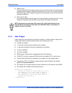
POST images are expected, but not required, to return to the boot loader. Upon return, the boot
loader proceeds with the scan for an executable alternate boot image. POST images that return
control to the boot loader must ensure that upon return, the state of the board is consistent with
the state that the board was in at POST entry. USER images should not return control to the
boot loader.
6.7.5 Alternate Boot Images and Safe Start
Some later versions of MOTLoad support alternate boot images and a safe start recovery
procedure. If safe start is available on the MVME7100, alternate boot images are supported.
With alternate boot image support, the boot loader code in the boot block examines the upper
8 MB of the flash bank for alternate boot images. If an image is found, control is passed to the
image.
6.7.6 Boot Image Firmware Scan
The scan is performed by examining each 1 MB boundary for a defined set of flags that identify
the image as being POST, USER, or Alternate MOTLoad. POST is a user-developed Power On
Self Test that would perform a set of diagnostics and then return to the boot loader image.
USER would be a boot image, such as the VxWorks bootrom, which would perform board
initialization. A bootable VxWorks kernel would also be a USER image. Boot images are not
restricted to being 1 MB or less in size; however, they must begin on a 1 MB boundary within
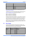
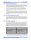
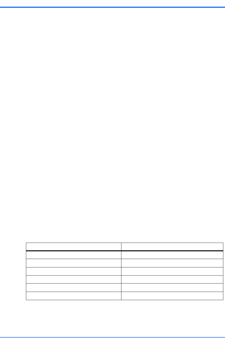
the 8 MB of the scanned flash bank. The flash bank structure is shown below:
The scan is performed downwards beginning at the location of the first possible alternate image
and searches first for POST, then USER, and finally Alternate MOTLoad images. In the case of
multiple images of the same type, control is passed to the first image encountered in the scan.
Address Usage
0xFFF00000 to 0xFFFFFFFF Boot block. Recovery code.
0xFFE00000 to 0XFFFFFFFF Backup MOTLoad image
0xFFD00000 to 0xFFDFFFFF First possible alternate image
0xFFC00000 to 0xFFCFFFFF Second possible alternate image
.... Alternate boot images
0xFF899999 to 0xFF8FFFFF Bottom of flash (flash size varies per product)


