


MVME7100 Single Board Computer Installation and Use (6806800E08A)
Functional Description DUART Interface
72
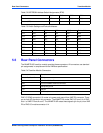
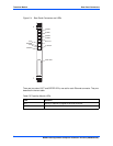
4.9 DUART Interface
The MVME7100 provides a front access asynchronous serial port interface using Serial Port 0
from the MC864xD DUART. The TTL-level signals SIN, SOUT, RTS and CTS from Serial Port
0 are routed through on-board RS-232 drivers and receivers to the mini DB-9 front panel
connector.
4.10 PCI-E Port 0
One 8x PCI-E port from the MC864xD processor is connected to a five port PEX8533 PCI-E
switch. Each downstream port from the PCI-E switch is connected to a PCI/PCI-X bridge. The
MVME7100 implements four separate PCI/PCI-X bus segments.
PCI-X bus 1 connects to PMC site 1 using a PEX8114 bridge and is configured dynamically,
with onboard logic, to operate in 33/66 MHz PCI or 66/100 MHz PCI-X mode depending on the
PMC installed.
PCI-X bus 2 connects to PMC site 2 using a PEX8114 bridge and is configured dynamically,
with onboard logic, to operate in 33/66 MHz PCI or 66/100 MHz PCI-X mode depending on the
PMC installed.
PCI-X bus 3 connects to the Tsi148 using a PEX8114 bridge and is configured for 133 MHz
PCI-X mode.
PCI bus 4 connects to the USB controller using a PEX8112 bridge and is configured for 33 MHz
PCI mode since the USB controller is only 33 MHz capable.
4.10.1 VME Controller
The VMEbus interface for the MVME7100 is provided by the Tsi148 VMEbus controller. The
Tsi148 provides the required VME, VME extensions, and 2eSST functions. TI
SN74VMEH22501 transceivers are used to buffer the VME signals between the Tsi148 and the
VME backplane. Refer to the Tsi148 user's manual for additional details and/or programming
information.
4.10.2 USB
The NEC uPD720101 USB 2.0 Host Controller provides USB ports with integrated transceivers
for connectivity with any USB compliant device or hub. USB channel 1 is routed to a single USB
connector located at the front panel. DC power to the front panel USB port is supplied via a USB
power switch which provides soft-start, current limiting, over current detection, and power
enable for port 1. Refer to the uPD720101 datasheet for additional details and/or programming
information.