


PMC Input/Output Module Transition Module
MVME7100 Single Board Computer Installation and Use (6806800E08A)
79
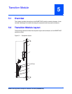
5.6 PMC Input/Output Module
If a PMC Input/output Module (PIM) has already been installed on the MVME7216E, or you are
installing a transition module as it has been shipped from the factory, disregard this procedure
and refer to Transition Module on page 40.
Procedure
For PIM installation, perform the following steps:
1. Attach an ESD strap to your wrist. Attach the other end of the ESD strap to the
chassis as a ground. The ESD strap must be secured to your wrist and to ground
throughout the procedure.
2. Carefully remove the transition module from its packaging and lay it flat on a stable
surface.
3. Remove the PIM filler from the front panel of the transition module.
4. Slide the face plate (front bezel) of the PIM module into the front panel opening from
behind and place the PIM module on top of the transition module, aligned with the
appropriate two PIM connectors. The two connectors on the underside of the PIM
module should then connect smoothly with the corresponding connectors on the
transition module (J10 and J14).
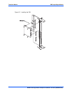
5. Insert the four short Phillips screws, provided with the PIM, through the holes on the
bottom side of the transition module into the PIM front bezel and rear standoffs.
Tighten the screws.
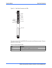
Refer to the following figure for proper screw/board alignment. The example below
may not accurately represent your MVME7100.