


Connectors Controls, LEDs, and Connectors
MVME7100 Single Board Computer Installation and Use (6806800E08A)
61
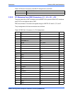
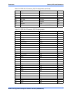
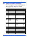
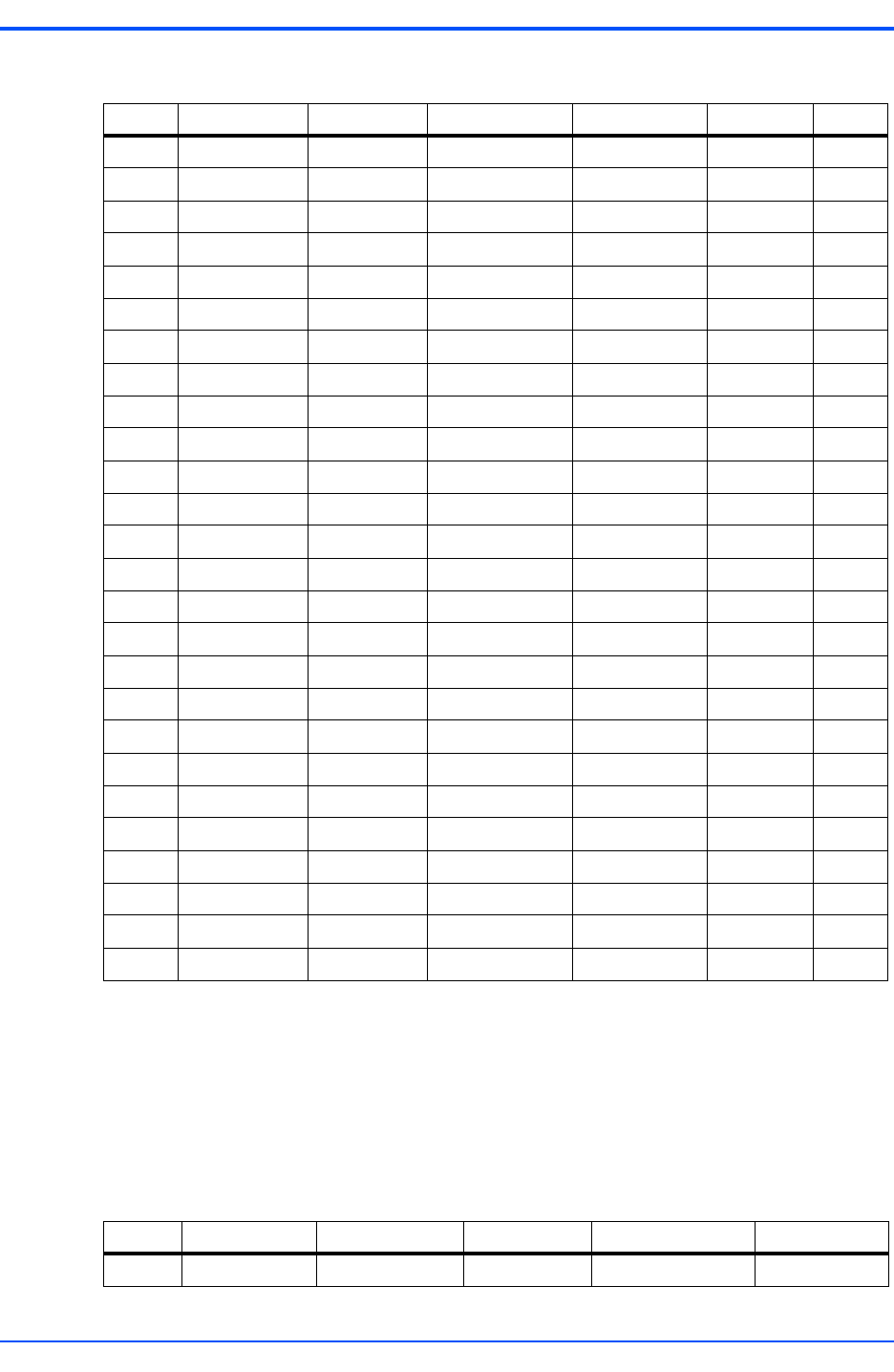
3.3.3.6 VMEbus P2 Connector
The VME P2 connector is a 160-pin DIN. Row B of the P2 connector provides power to the
MVME7100 and to the upper eight VMEbus address lines and additional 16 VMEbus data lines.
The Z, A, C, and D pin assignments for the P2 connector are the same for both the MVME7100
and MVME7216E, and are as follows:
7 Reserved D06 BG1OUT* D14 Reserved 7
8 GND D07 BG2IN* D15 Reserved 8
9 Reserved GND BG2OUT* GND GAP_L 9
10 GND SYSCLK BG3IN* SYSFAIL* GA0_L 10
11 Reserved GND BG3OUT* BERR* GA1_L 11
12 GND DS1* BR0* SYSRESET* Reserved 12
13 Reserved DS0* BR1* LWORD* GA2_L 13
14 GND WRITE* BR2* AM5 Reserved 14
15 Reserved GND BR3* A23 GA3_L 15
16 GND DTACK* AM0 A22 Reserved 16
17 Reserved GND AM1 A21 GA4_L 17
18 GND AS* AM2 A20 Reserved 18
19 Reserved GND AM3 A19 Reserved 19
20 GND IACK* GND A18 Reserved 20
21 Reserved IACKIN* SERA A17 Reserved 21
22 GND IACKOUT* SERB A16 Reserved 22
23 Reserved AM4 GND A15 Reserved 23
24 GND A07 IRQ7* A14 Reserved 24
25 Reserved A06 IRQ6* A13 Reserved 25
26 GND A05 IRQ5* A12 Reserved 26
27 Reserved A04 IRQ4* A11 Reserved 27
28 GND A03 IRQ3* A10 Reserved 28
29 Reserved A02 IRQ2* A09 Reserved 29
30 GND A01 IRQ1* A08 Reserved 30
31 Reserved -12V +5VSTDBY +12V GND 31
32 GND +5V +5V +5V +5V 32
Table 3-13 VMEbus P1 Connector Pin Assignments (continued)
ROW Z ROW A ROW B ROW C ROW D
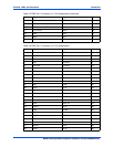
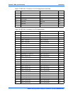
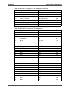
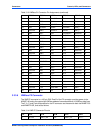
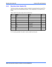
Table 3-14 VME P2 Connector Pinouts
Pin P2-Z P2-A P2-B P2-C P2-D
1 SP1RX PMC1_IO2 +5V PMC1_IO1 E1-1+