3
Controller Layout
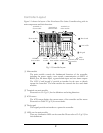
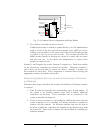
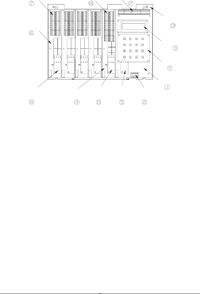
Figure 1.1 shows the layout of the EverAccess Flex Series Controller along with its
main components and their functions.
Fig. 1.1 Controller Layout
(1) Main module
The main module controls the fundamental functions of the controller,
including the power supply, event records, communication via RS232 or
RS485 port, fire alarm input, a general alarm input and two alarm outputs.
The LCD ③ and keypad ④ provide an interface for the users to directly
operate the controller. The main module also controls the door and alarm
modules.
(2) Terminals on main module
Please refer to Ch 2 (p 11) for the definitions and wiring directions.
(3) LCD screen
The LCD screen displays the current status of the controller and the menu.
Please refer to Table 2.1 (p 12) for more details.
(4) The keypad
The keypad provides an interface to operate the controller.
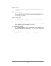
(5) LEDs on the main module
There are 4 indication LEDs on the controller. Please refer to Ch 2 (p 12) for
their definitions.
T
erminals on
door module
T
erminals on
alarm module
T
erminals on
main module
2*16
L
CD
Base board
Door module
LEDs on
door module
LEDs on
alarm module
A
larm
module
LEDs on
main module
T
erminals on
main module
Main
module
Key
p
ad


