13
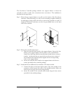
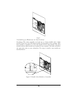
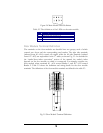
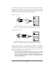
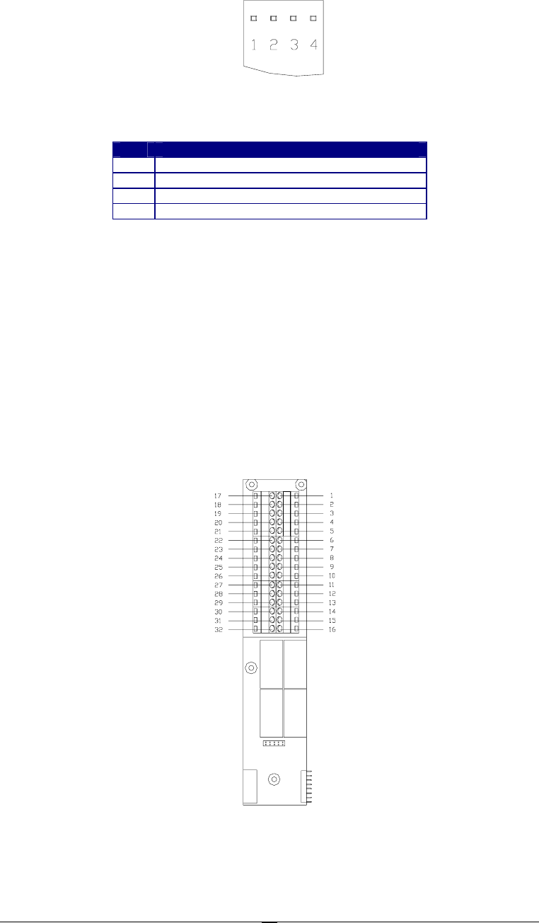
Figure 2.4 Main Module LED Definition
Table 2.2 The definition of the LEDs on the main module
LED Meaning
1 The power is on when the light is on
2 Fire alarm when the light is on
3 Data is received when the light is on
4
Data is transmitted when the light is on
Door Module Terminal Definition
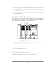
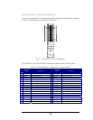
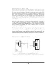
The terminals on the door modules are classified into two groups, each of which
controls two doors and the corresponding card readers. The right side terminals
(indexed from #1~#16) control one reader, while the left side terminals (indexed
from #17~#32) are responsible for the 2
nd
reader, as shown Fig. 3.5. As described in
the “reader/door index conversion” section of the manual, the reader’s index
depends on the door module to which it is connected. For example, consider one
door module where terminals #1 ~#16 control Reader 1, and #17~#32 control
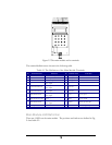
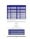
Reader 2. Table 2.3 shows the definition and wiring details for the door module
terminals. The definitions of the door module terminals are defined in the table 2.3.
Fig. 2.5 Door Module Terminal Definition


