50
Alarm output configuration for all events under this menu follows the similar style in
the above example.
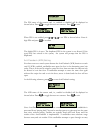
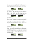
Note: in the above example all 4 door modules are installed. In case less than 4 door
modules are installed, positions corresponding to uninstalled modules are replaced
with minus sign ‘-’, as shown below:
The figure shows the case where 3 door modules are installed. Alarm output status on
the main module is stilled configured by pressing numeric key 9,0.
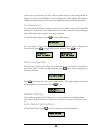
Enter Extended Alarm Setting Sub-menu
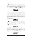
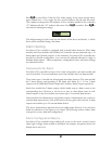
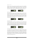
Under Alarm Setting menu, press
once to bring up the following window:
Press
ENT
to enter Extended Alarm Setting submenu. The first submenu is for fire
alarm outputs. Use
and
to choose from different alarm menus for different
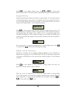
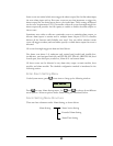
events. Alarm output configuration for all events is basically the same. As an example,
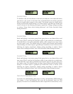
alarm output configuration for invalid card event is introduced below. The figure
below shows the menu interface:
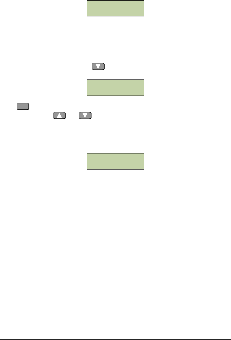
The upper line indicates the card to be configured, i.e., invalid card. The first 8
characters of the lower line are alarm output status of this event on the alarm module.
Y indicates there is alarm output (relay energized) and N indicates there is no alarm
output (relay not energized).
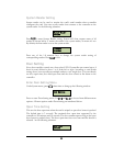
In the above example, alarm output relays on all alarm modules will not be energized
and no alarm outputs will be generated due to the invalid card event.
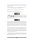
In this menu, press numeric key 1~8 to toggle the alarm output status of this event
on the alarm module between Y and N. Alarm output configuration for all events
under this menu follows the similar style in the above example.
In what follows, definitions of all events and configuration methods are introduced.
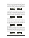
Fire Alarm
For correspondence between fire alarm and doors, please refer to “connection to fire
alarm input” in chapter 4. In case of fire alarm input, controller will generate fire
Invalid Card
RNNNNNNN-NN
Extended Alarm
Setting
Invalid Card
NNNNNNNN


