16
Alarm Module LED Definition
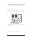
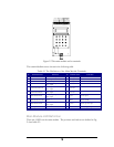
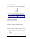
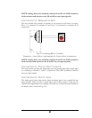
There are 8 LED indicators on each door module. The positions and indexes are
shown in Fig. 2.8. The definitions of the LED indicators are presented in Table 2.6.
Fig. 2.8 Alarm Module LED Definition
The definitions of LEDs on the alarm module are defined in the following table:
Table 2.6 The Definition of the LED Indication on the Alarm Module
LED Meaning LED Meaning
1 Alarm 1 5 Alarm 5
2 Alarm 2 6 Alarm 6
3 Alarm 3 7 Alarm 7
4 Alarm 4 8 Alarm 8
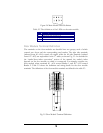
The alarm LED has four different indications:
Light off: No alarm alert for the alarmed zone.
Light flashes slowly: The alarmed zone is in the alert delay stage.
Solid light on: The alarm alert is on for the alarmed zone
Light flashes quickly: The alarmed zone is in danger; alarm signal is input
Install and Connecting the Readers
The card readers chosen for the access control system must be mounted near each
door and connected directly to the door module(s) in the controller. Each module
can accommodate two readers. The general procedure is described below:
1. Mount each reader, following the instructions included with the reader.
Typically, this will include drilling two holes in the mounting wall, and
then using the reader mounting hardware to secure the reader to the
mounting wall.
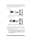
2. Once the readers are mounted, connect them to the door module. For
wiring definitions, please see previous sections in this manual.


