


ISS 408 Integrated Seamless Switcher • Installation 7
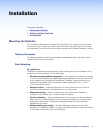
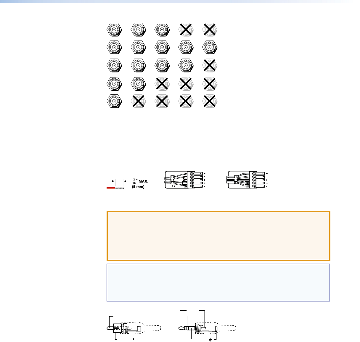
H/HV
RGBHV
Video
RGsB or
Component
Video
S-Video Composite
Video
RGBS or
RGBcvS
Video
V
H/HV
V
H/HV
V
H/HV
V
H/HV
V
R/R-Y
G/Y
VID
B/C
B-Y
R/R-Y
G/Y
VID
B/C
B-Y
R/R-Y
G/Y
VID
B/C
B-Y
R/R-Y
G/Y
VID
B/C
B-Y
R/R-Y
G/Y
VID
B/C
B-Y
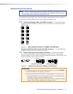
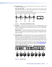
Figure 4. Connections for Various Input Video Formats
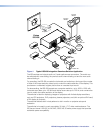
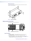
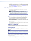
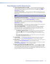
c Input audio connectors — Connect balanced or unbalanced stereo or mono audio
sources to these 3.5 mm, 5-pole captive screw connectors. Connectors are included
with the seamless switcher, but you must supply the audio cable. Figure 5 shows how
to wire a connector for the appropriate input type.
Unbalanced Stereo Input
Balanced Stereo Input
Do not tin the wires!
Tip
Ring
Tip
Ring
Sleeves
Tip
Sleeve
Sleeve
Tip
LR
LR
Figure 5. Captive Screw Connector Wiring for Inputs
ATTENTION: The length of exposed wires is critical. The ideal length is 3/16 inch
(5 mm).
• If the stripped section of wire is longer than 3/16 inch, the exposed wires may
touch, causing a short circuit between them.
• If the stripped section of wire is shorter than 3/16 inch, wires can be easily
pulled out even if tightly fastened by the captive screws.
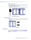
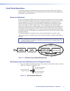
NOTE: When making connections for the seamless switcher from existing audio
cables (see figure 6). A mono audio connector consists of the tip and sleeve. A
stereo audio connector consists of the tip, ring, and sleeve. The tip, ring, and
sleeve wires are also shown on the captive screw audio connector diagram,
figure 5.
Tip (+)
Sleeve ( )
Sleeve ( )
Ring (
-
)
Tip (+)
RCA Connector
3.5 mm Stereo Plug Connector
(balanced)
Figure 6. Typical Audio Connectors
The audio level for each input can be individually set, via the front panel, the Ethernet
link, or the RS-232 link, to ensure that the level on the output does not vary from
input to input. See the applicable portions of the “Operation” section (see page 18),
“Programming Guide” section (see page 45), and “Switcher Software” section (see
page 54).