


ISS 408 Integrated Seamless Switcher • Maintenance and Modifications 69
4. Remove the top two front panel screws.
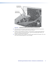
5. Lift the top cover straight up approximately 5 inches until you can access the fan power
cords.
ATTENTION: Do not touch any switches or other electronic components inside
the ISS. Doing so could damage the switcher. Electrostatic discharge (ESD)
can damage IC chips even though you cannot feel it. You must be electrically
grounded before proceeding with firmware replacement.
A grounding wrist strap is recommended.
6. Disconnect the two fan power cords from connectors J8 and J13 on the main board.
7. Lift the top cover out of the way.
8. Perform the desired maintenance procedure. See “Installing a Firmware Upgrade” below
or “Installing a DVI Output Card” on page 70.
9. Reconnect the two fan power cords to connectors J8 and J13 on the main board. It
does not matter which fan is connected to which connector.
10. Replace the top cover on the ISS.
11. Fasten the top cover with the screws that were removed in step 3 and step 4.
12. Rack mount the switcher, if desired, and reconnect all cables.
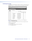
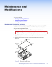
Installing a Firmware Upgrade
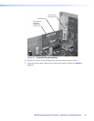
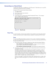
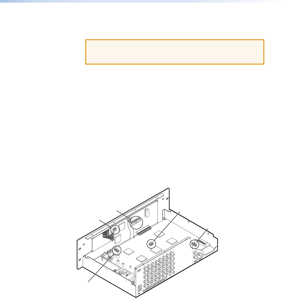
In some cases the ISS’s firmware may require replacement with an updated version. There
are nine user-replaceable firmware chips (see figure 7-2): U1, U2, and U6 on the front panel
circuit board and U98, U99, U100, U101, U102, and U103 on the main circuit board. The
U-numbers are printed on the circuit boards. Extron recommends that you send the unit in
to Extron for service and updates.
1
2 3
4
5
6
7
8
10
0
-
240
50
/6
0 H
z
1.2A MAX.
R
1
G
B
H
/H
V
R
2
G
B
H
/HV
R
3
G
B
H
/HV
R
IN
PU
TS
4
G
B
H
/HV
R
5
G
B
H
/H
V
R
6
G
B
H
/HV
R
7
G
B
H
/H
V
R
8
G
B
H
/HV
B
H
/H
V
V
H
/H
V
V
Extron
ISS 408
Switcher
U1
U2
U100
U101
U6
U102
U103
U98
U99
Figure 54. ISS Firmware Chip Locations