


ISS 408 Integrated Seamless Switcher • Maintenance and Modifications 70
• Chips U1 and U2 are replaced as a pair.
• Chip U6 is replaced alone.
• Chips U98, U99, U100, and U101 are replaced as a set.
• Chips U102 and U103 are replaced as a pair.
ATTENTION: Changes to firmware must be performed by authorized service
personnel only. Some ISS firmware updates must be performed at the Extron
factory.
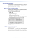
Replace firmware in the ISS as follows:
CAUTION: Electric shock hazard. To prevent electric shock, always unplug the ISS
from the AC power source before opening the enclosure.
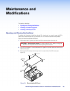
1. Open the switcher (see “Opening and Closing the Switcher” on page 68).
2. Locate the firmware chips to be replaced on the main or front panel circuit board (see
figure 54).
3. After you are electrically grounded, use a DIP chip puller to grasp each IC chip and pull
it out of the sockets.
4. Align the slots of each new firmware chip with the angled corners of the socket in the
same orientation as the old chip. Gently, but firmly, press the chip into place in the
socket.
5. Close the switcher (see “Opening and Closing the Switcher” starting with step 9 on
page 69).
Installing a DVI Output Card
You can install an optional digital visual interface (DVI) output card in the ISS. With the
card installed, an additional program output is available as DVI video on a standard DVI
connector. This program output is in addition to the standard RGB video on BNC connector
and 15-pin HD connectors. Extron recommends that you send the unit to Extron for service
and updates.
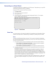
Install an optional DVI output card in the ISS as follows:
ATTENTION: Changes to electronic components must be performed by authorized
service personnel only.
CAUTION: Electric shock hazard. To prevent electric shock, always unplug the ISS
from the AC power source before opening the enclosure.
1. Open the switcher (see “Opening and Closing the Switcher” on page 68).
ATTENTION: Do not touch any switches or other electronic components inside the
ISS. Doing so could damage the ISS. Electrostatic discharge (ESD) can damage
IC chips even though you cannot feel it. You must be electrically grounded before
proceeding with any electronic component replacement. A grounding wrist strap
is recommended.
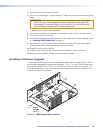
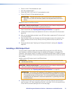
2. Locate the DVI output card connector opening on the rear panel and the DVI output
card connector J14. When viewed from the front, connector J14 is in the far left corner
of the main circuit board (see figure 55 on the next page).