


ISS 408 Integrated Seamless Switcher • Installation 8
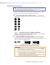
Standard Output Connections
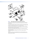
NOTE: The two Program video outputs, consisting of five BNC connectors and a 15-pin
HD connector, output the identical video signal and the same sync format. The two
Preview video outputs are also identical to each other.
The Program connectors (d) output the video image for the program monitor or projector.
The Preview connectors (e) output the video image for the local monitor.
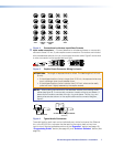
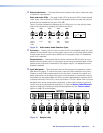
de Preview and Program video output BNC connectors — Connect RGB video
displays to these female BNC connectors. Figure 7 shows how to connect the various
video formats.
H/HV
R
G
B
H/HV
RGBHV
Video
RGBS
Video
V
R
G
B
V
Figure 7. BNC Output Connections for RGBHV and RGBS Video
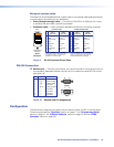
Program and Preview video output 15-pin HD connectors — Connect RGB video
displays to these two female 15-pin HD connectors.
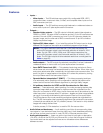
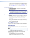
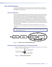
fg Preview and Program audio output connectors — Connect audio devices,
such as an audio amplifier or powered speakers, to these 3.5 mm, 5-pole captive
screw connectors. The connectors output the selected unamplified, line level audio. See
figure 8 to properly wire an output connector.
Unbalanced Stereo Output Balanced Stereo Output
Do not tin the wires!
Tip
Ring
Tip
Ring
Sleeves
Tip
No Ground Here
No Ground Here
Tip
Sleeves
LR
LR
Figure 8. Captive Screw Connector Wiring for Audio Output
ATTENTION:
• For unbalanced audio, connect the sleeves to the ground contact. DO NOT
connect the sleeves to the negative (-) contacts.
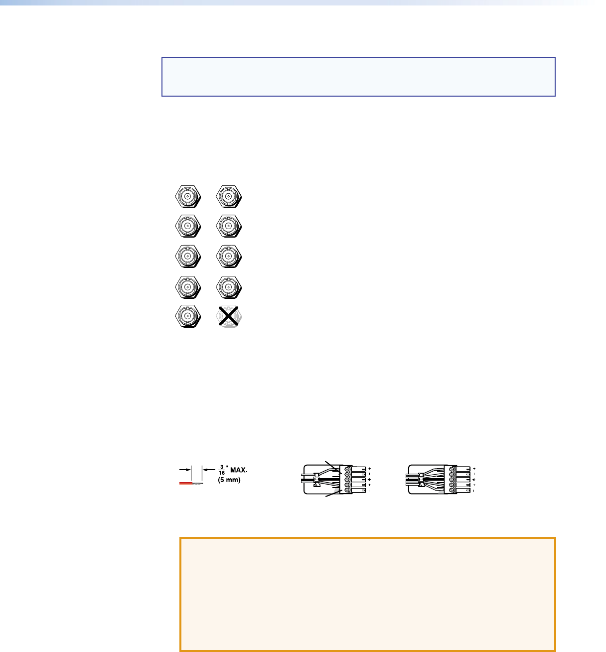
• The length of exposed wires is critical. The ideal length is 3/16 inch (5 mm).
• If the stripped section of wire is longer than 3/16 inch, the exposed wires
may touch, causing a short circuit between them.
• If the stripped section of wire is shorter than 3/16 inch, wires can be easily
pulled out even if tightly fastened by the captive screws.