


ISS 408 Integrated Seamless Switcher • Installation 10
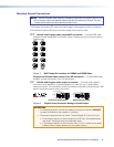
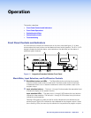
Wiring the network cable
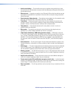
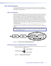
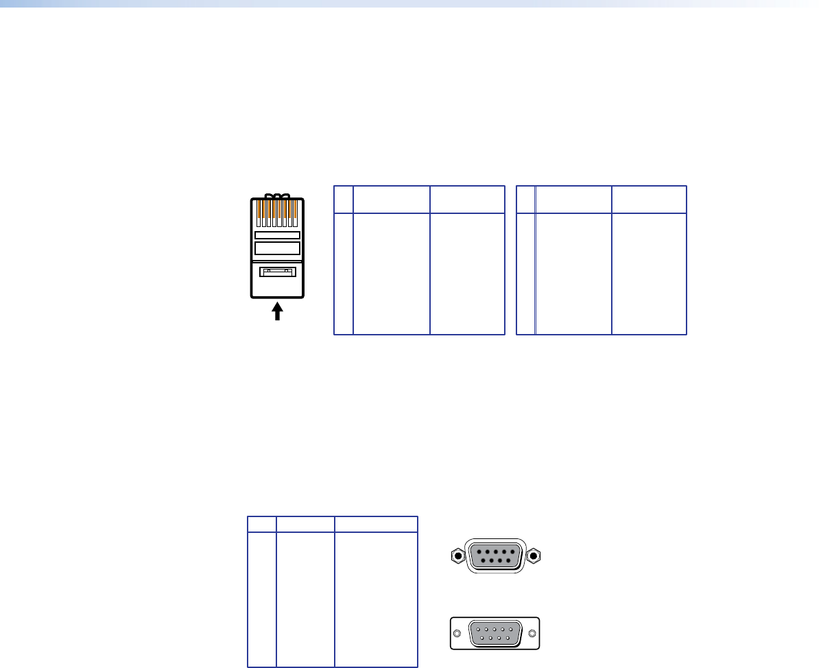
The cable can be terminated as either a patch cable or a crossover cable (see figure 9) and
must be properly terminated for your application:
• Patch (straight through) cable — Connection of the ISS to an Ethernet hub, router,
or switcher that also hosts a controlling computer
• Crossover cable — Direct connection between the ISS and a controlling computer
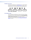
A cable that is wired as T568A at one end
and T568B at the other (Tx and Rx pairs
reversed) is a "crossover" cable.
A cable that is wired the same at both ends is
called a "straight-through" cable, because
no pin/pair assignments are swapped.
12345678
RJ-45
Connector
Insert Twisted
Pair Wires
Pins:
Crossover Cable Straight-through Cable
Pin
1
2
3
4
5
6
7
8
Wire color
White-green
Green
White-orange
Blue
White-blue
Orange
White-brown
Brown
Wire color
T568A T568B
End 1 End 2 End 1 End 2
White-orange
Orange
White-green
Blue
White-blue
Green
White-brown
Brown
Pin
1
2
3
4
5
6
7
8
Wire color
White-orange
White-green
Blue
White-blue
White-brown
Brown
Wire color
T568BT568B
White-orange
OrangeOrange
White-green
Blue
White-blue
GreenGreen
White-brown
Brown
Figure 9. RJ-45 Connector Pinout Table
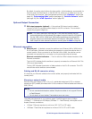
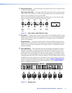
RS-232 Connection
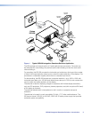
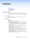
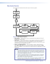
j Remote port — Connect a host device, such as a computer or touch panel control, to
the Integration Seamless Switcher via this 9-pin D connector for serial RS-232 control
(see figure 10).
RS-232 FunctionPin
1
2
3
4
5
6
7
8
9
—
TX
RX
—
Gnd
—
—
—
—
Not used
Transmit data
Receive data
Not used
Signal ground
Not used
Not used
Not used
Not used
51
9
5
9
6
Female
Male
1
6
Figure 10. Remote Port Pin Assignments
Configuration
The ISS can be configured using either the front panel controls, the SIS, or the Windows
Control program (see the “Operation” section on page 17, the “Programming Guide”
section on page 41, the “Switcher Software” section on page 52, and the “HTML
Operation” section on page 64).