


ISS 408 Integrated Seamless Switcher • Maintenance and Modifications 71
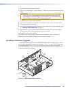
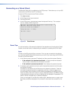
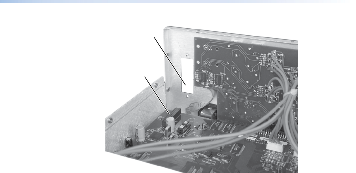
DVI Output Card
Connector J14 on
Main Circuit Board
DVI Output Card
Connector Opening
in ISS Rear Panel
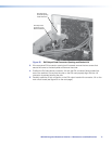
Figure 55. DVI Output Card Connector Opening and Socket J14
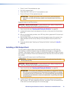
3. If the rear panel DVI connector opening is still covered, remove the two screws that
secure the cover to the back panel and remove the cover.
4. Position the DVI card above connector J14 with the DVI connector facing toward the
rear of the switcher. Ensure that the pins on the DVI card properly align with the J14
connector to prevent bending the pins.
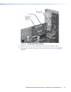
5. Carefully mate the 45-pin connector on the DVI output board with connector J14 on the
main circuit board (see figure 56 on the next page).