HYDRA
Service Manual
3-14
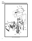
3-24. Install the Main PCA
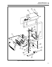
1. Fit the Main PCA (H) so that the chassis guides pass through notches on both sides
of the pca. Then slide the pca back until it is snug against the Rear Panel.
2. Replace the RS-232 connector screws (T) on the rear of the chassis. Use a 3/16-inch
nut driver to tighten the connector hardware.
3. Fasten the Main PCA to the chassis with two 6-32, 1/4-inch panhead screws (U).
4. Connect the transformer cable at connector J3 on the Main PCA. Verify that the
connector is aligned correctly (all three pins connected.)
5. Plug the Front Panel cable onto its connector (J2) on the Main PCA.
6. From the Rear Panel, push the ALARM OUTPUTS and DIGITAL I/O terminal
strips onto their appropriate connectors.
3-25. Install the IEEE-488 Option (2620A Only)
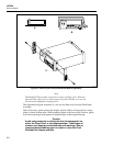
Both the instruction sheet provided with the IEEE-488 Option and Section 7 of this
manual fully describe installation. The following instructions provide installation
procedure essentials. If necessary, refer to Section 7, paying particular attention to
Figures 7-2 and 7-3.
1. Place the IEEE-488 PCA (N) into position so that the edge of the pca fits into the
chassis guide. Then line up connecting pins with the matching connector on the
Main PCA, and slide the pca into position.
2. Install the single 6-32, 1/4-inch panhead Phillips screw in the corner of the IEEE-488
PCA.
3. If necessary, attach the rear panel connector using a 7-mm nut driver.
4. At the pca, attach the ribbon cable leading from the rear panel connector.
3-26. Install the Memory PCA (2625A Only)
Note
The Memory PCA and the IEEE-488 PCA occupy the same position and
use the same connection to the Main PCA. The Memory PCA is a standard
part of the Hydra Data Logger (Model 2625A). The IEEE-488 PCA is not
available with the 2625A but is optional with the Hydra Data Acquisition
Unit (Model 2620A).
1. Place the Memory PCA into position so that the edge of the pca fits in the chassis
guide. Then line up connecting pins with the matching connector on the Main PCA,
and slide the pca into position.
2. Install the single 6-32, 1/4-inch panhead Phillips screw in the corner of the Memory
PCA.


