


Diagnostic Testing and Troubleshooting (2620A/2625A)
Power Supply Troubleshooting
5
5-9
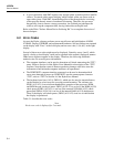
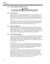
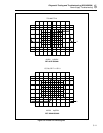
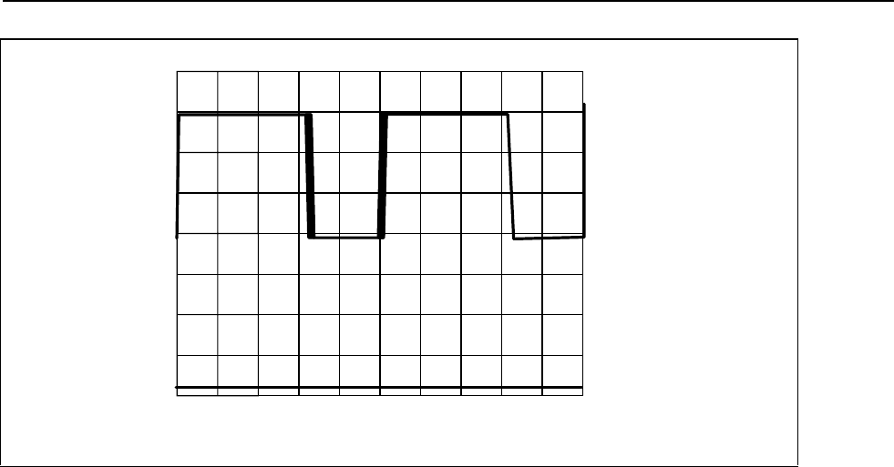
U9-7 and T2-2
5V/DIV
0V
20V
2 µS/DIV
Normal Load
s33f.eps
Figure 5-2. 5-Volt Switching Supply
If no square wave is present at A1U9-7, the oscillator can be checked by looking at the
signal at A1U9-3. The oscilloscope should be ac-coupled for this measurement. This
waveform should be a sawtooth signal with an amplitude of 0.6V p-p and a period of
approximately 14 us. Failure of the oscillator is usually caused by a defective capacitor
A1C21 or defective A1U9.
The output current of the 5-volt switching supply can be determined by measuring the
voltage across the current limit current sense resistors (A1R29, A1R30 and A1R31). The
current shunt is approximately 0.167 ohms. With line voltage at 120V ac and the
instrument not actively measuring, typical voltages across the current sense resistors are
as follows:
• 2620A Instrument without options: 28 mV
• 2620A Instrument with IEEE-488 Option: 50 mV
• 2625A Instrument: 28 mV
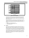
5-9. Inverter
Use an oscilloscope to troubleshoot the inverter supply. The outputs of the inverter
supply are -5V dc, -30V dc, and 5.4V ac outguard, and +5.3V dc, -5.4V dc, and +5.6V dc
inguard. Refer to Figure 5-3. The signal at the drains of the two inverter switch FETs
(A1Q7 and A1Q8) should be a 10V peak square wave with a period of approximately 18
us. The gate signal is a 5.1V peak square wave with rounded leading and trailing edges.
The leading edge has a small positive rounded pulse with an amplitude of 1.8V peak and
a pulse width of about 0.3 µs. The signal at A1U22-5 and A1U22-6 is a symmetrical
square wave with an amplitude of 5.1V peak and a period of about 18 µs. The negative-
going trailing edge of both square waves is slower than the rising edge and has a small
bump at about 1.5 volts. The signal at A1U22-3 (TP14) is a symmetrical square wave
with a period of about 9 µs.