


Theory of Operation (2620A/2625A)
Detailed Circuit Description
2
2-27
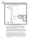
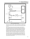
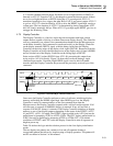
The current through the selected integrator input resistor charges integrator capacitor
A3C13, with the current dependent on the buffer output voltage. After the integrate
phase, the buffer is connected to the opposite polarity reference voltage, and the
integrator integrates back toward zero capacitor voltage until the comparator trips. An
internal counter measures this variable integrate time. If the a/d converter input voltage
is too high, the integrator overloads and does not return to its starting point by the end of
the measurement phase. Switch S77 is then turned on to discharge integrate capacitor
A3C13.
The reference voltage used during the variable integrate period for voltage (and high
ohms) conversions is generated from zener reference diode A3VR1, which is time and
temperature stable. The reference amplifier in the Analog Measurement Processor, along
with resistors A3R15, A3R18, and A3R21, pulls approximately 2 mA of current through
the zener. Resistors in network A3Z2 divide the zener voltage down to the reference
1.05V required by the A/D Converter.
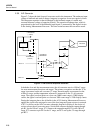
2-60. Inguard Microcontroller Circuitry
The Microcontroller, A3U9, with its internal program memory and RAM and associated
circuitry, controls measurement functions on the A/D Converter PCA and communicates
with the Main (outguard) processor.
The Microcontroller communicates directly with the A3U8 Analog Measurement
Processor using the CLK, CS, AR, and AS lines and can monitor the state of the analog
processor using the FC[0:7] lines. Filter zeroing is controlled by the ZERO signal. The
open thermocouple detect circuitry is controlled by the OTCCLK and OTCEN lines and
read by the OTC line. The Microcontroller also communicates with the Main (outguard)
processor serially using the IGDR line to receive and the IGDS line (driven by A3Q1) to
send.
The channel and function relays are driven to the desired measurement state by signals
sent out through microcontroller ports 1, 3, 4, 6, and 7.
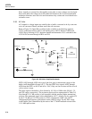
On power up, the reset/break detect circuit made up of quad comparator A3U1,
capacitors A3C1 and A3C2, and resistors A3R1 through A3R6 and A3R8 resets the
Microcontroller through the RESET* line. When a break signal is received from the
outguard processor, the inguard A3U9 is again reset. Therefore, if Microcontroller
operation is interrupted by line transients, the outguard can regain control of the inguard
by resetting A3U9.
2-61. Channel Selection Circuitry
Measurement input channel selection is accomplished by a set of latching 4-form-C
relays organized in a tree structure. Relays A3K5, A3K6, and A3K8 through A3K14
select among channels 1 through 20. Relay A3K7 disconnects rear input channels 1
through 20 from the measurement circuitry between measurements. Relay A3K3
switches in the front panel channel 0 or the rear channels. Inductors A3L1 through
A3L24 reduce EMI and current transients.
Selection between 2-wire and 4-wire operation for ohms measurements is performed by
latching 2-form-C relays (A3K1 and A3K2.) These relays also serve to select a voltage
or thermocouple rear input channel from either channels 1 through 10 or channels 11
through 20.