Introduction and Specifications
Specifications
1
1-19
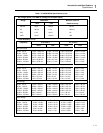
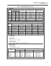
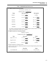
Table 1-3. 2620A/2625A Specifications (cont)
AC Signal Crosstalk into an Ohms Channel
AC Frequency = 50, 60 Hz, ±0.1%
OHMS Error Ratio =
Ohmss error
VACrms crosstalk
()
()
Range Ratio (worst case) Ratio (typical)
300.00Ω 3.3 x 10
-5
Ohms
VACrms
No Effect
3.000 kΩ 2.4 x 10
-6
kOhms
VACrms
6.7 x 10
-7
kOhms
VACrms
30.000 kΩ 3.1 x 10
-4
kOhms
VACrms
8.4 x 10
-5
kOhms
VACrms
300.00 kΩ 5.6 x 10
-3
kOhms
VACrms
3.7 x 10
-3
kOhms
VACrms
3.0000 MΩ 3.8 x 10
-4
MOhms
VACrms
3.8 x 10
-5
MOhms
VACrms
10.000 MΩ 1.4 x 10
-3
MOhms
VACrms
4.3 x 10
-4
MOhms
VACrms
For example, to find the typical effect of a 60 Hz, 100V ac signal on another channel for the 30 kΩ
range, you would calculate: 100 X 8.4 X 10
-5
= 0.008 kΩ.
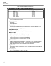
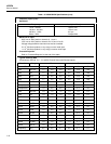
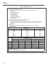
AC Signal Crosstalk into a Temperature Channel
Frequency = 50, 60 Hz
Temperature Error Ratio =
°
C error
VACrms crosstalk
()
()
Type Worst case Typical
Types J, K, E, T, N: 2.7 x 10
-3
°
C
VACrms
5.0 x 10
-4
°
C
VACrms
Types R, S, B, C: 1.1 x 10
-2
°
C
VACrms
2.0 x 10
-3
°
C
VACrms
Type PT (RTD): 8.6 x 10
-5
°
C
VACrms
No Effect
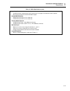
AC Signal Crosstalk into a Frequency Channel
Frequency measurements are unaffected by crosstalk as long as the voltage-frequency product is kept
below the following limits:
Worst Case Typical
V x Hz Product Limit 3.7 x 10
4
(V x Hz) 1.0 x 10
6
(V x Hz)
1
These valkues assu;me no more than 1000 pF of capacitance between either end of the resistor (HI and LOW) and earth groung.


