HYDRA
Service Manual
1-4
1-4. Organization of the Service Manual
This manual focuses on performance tests, calibration procedures, and component-level
repair of each of the instruments. To that end, manual sections are often interdependent;
effective troubleshooting may require not only reference to the troubleshooting
procedures in Section 5, but also some understanding of the detailed Theory of
Operation in Section 2 and some tracing of circuit operation in the Schematic Diagrams
presented in Section 8.
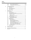
Often, scanning the table of contents will yield an appropriate place to start using the
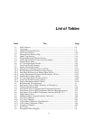
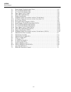
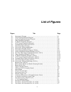
manual. A comprehensive table of contents is presented at the front of the manual; local
tables of contents are also presented at the beginning of each chapter for ease of
reference. If you know the topic name, the index at the end of the manual is probably a
good place to start.
The following chapter descriptions serve to introduce the manual:
Chapter 1. Introduction and Specifications
Introduces the instrument, describing its features, options, and accessories. This chapter
also discusses use of the Service Manual and the various conventions used in describing
the circuitry. Finally, a complete set of specifications is presented.
Chapter 2. Theory of Operation (2620A and 2625A)
This chapter first categorizes these instrument’s circuitry into functional blocks, with a
description of each block’s role in overall operation. A detailed circuit description is then
given for each block. These descriptions explore operation to the component level and
fully support troubleshooting procedures defined in Chapter 5.
Chapter 2A. Theory of Operation (2635A)
This chapter first categorizes the instrument’s circuitry into functional blocks, with a
description of each block’s role in overall operation. A detailed circuit description is then
given for each block. These descriptions explore operation to the component level and
fully support troubleshooting procedures defined in Chapter 5A.
Chapter 3. General Maintenance
Provides maintenance information covering handling, cleaning, and fuse replacement.
Access and reassembly procedures are also explained in this chapter.
Chapter 4. Performance Testing and Calibration
This chapter provides performance verification procedures, which relate to the
specifications presented in Chapter 1. To maintain these specifications, a full calibration
procedure is also presented.
Chapter 5. Diagnostic Testing and Troubleshooting (2620A and 2625A)
The troubleshooting procedures presented in this chapter rely closely on both the Theory
of Operation presented in Chapter 2, the Schematic Diagrams shown in Chapter 8, and
the access information provided in Chapter 3.
Chapter 5A. Diagnostic Testing and Troubleshooting (2635A)
The troubleshooting procedures presented in this chapter rely closely on both the Theory
of Operation presented in Chapter 2A, the Schematic Diagrams shown in Chapter 8, and
the access information provided in Chapter 3.
Chapter 6. List of Replaceable Parts
Includes parts lists for all standard assemblies. Information on how and where to order
parts is also provided.


